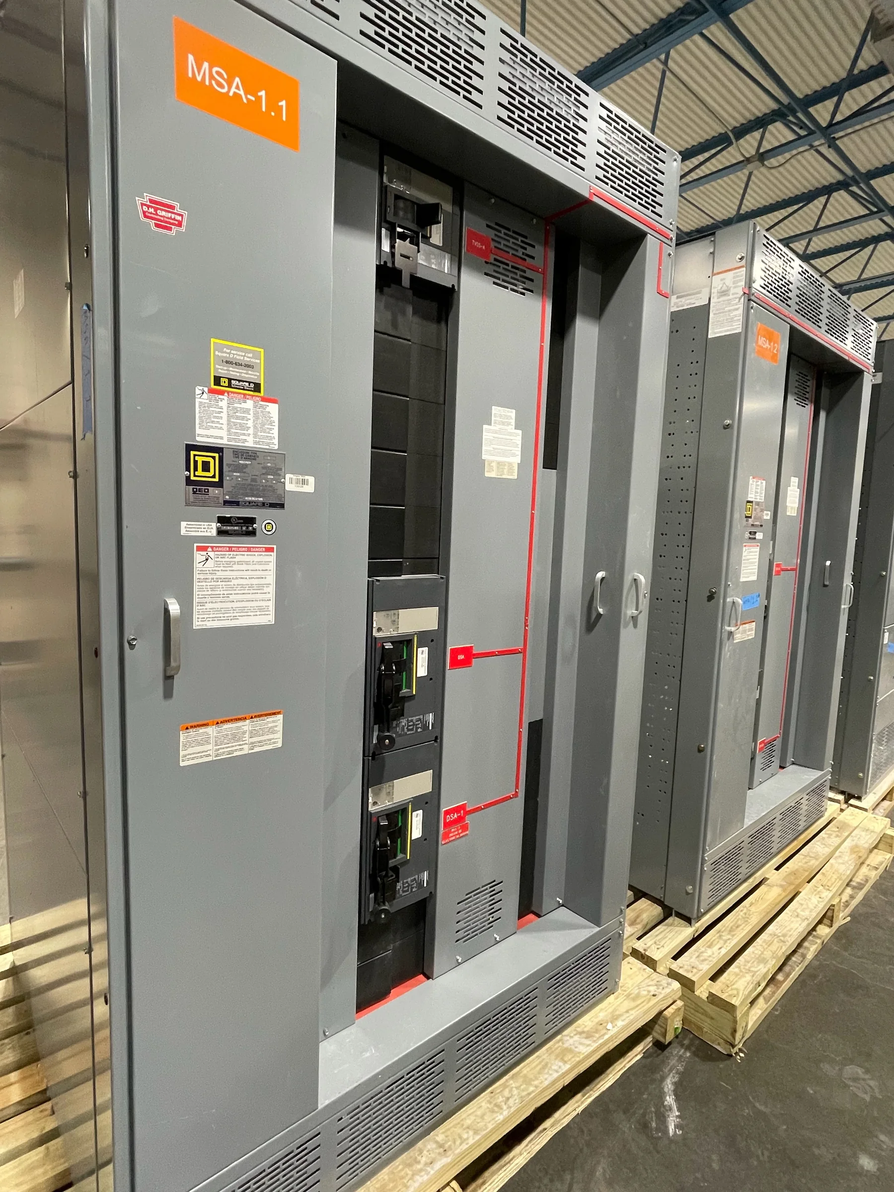
What Electrical Switchgear Does in a Distribution System
Electrical switchgear is an assembly of devices used to control, protect, and isolate electrical circuits. Depending on the system, it may include circuit breakers, switches, fuses, protective relays, metering, and associated bus conductors. Its job is not simply to route power: protection must identify abnormal conditions and interrupt the affected circuit, while isolation allows equipment to be safely taken out of service for inspection or maintenance. Switchgear sits at key points between a utility source, generators, transformers, and downstream loads. The equipment’s role depends on the project’s voltage, available fault current, grounding arrangement, operating sequence, and coordination with upstream and downstream devices. Establishing those conditions early helps engineers define an assembly that suits the actual distribution system rather than relying on a generic equipment description.
Switchgear, Switchboards, and Related Equipment
The terms switchgear and switchboard are sometimes used loosely, but they do not always describe the same construction or application. Low-voltage switchboards commonly distribute power through a lineup of sections containing protective devices and bus, while switchgear may use different construction and switching arrangements appropriate to its voltage and duties. Motor control centers, panelboards, and transfer equipment also serve distinct functions, even when they appear within the same facility. Choosing by name alone can create mismatches in fault-duty requirements, access, cable termination space, or the planned method of operation. For low-voltage switchboard projects, UL 891 may be a relevant standard for an appropriately evaluated assembly; it is not a blanket certification for every product or voltage class. Confirm the equipment category, applicable standards, and requested labeling against the project documents.


Engineering Inputs That Shape the Specification
A useful equipment specification gives manufacturers enough system information to evaluate the proposed configuration. Typical inputs include system voltage and frequency, available fault current, main and feeder arrangements, load data, grounding method, protective-device preferences, and the electrical one-line diagram. Engineers should also identify service conditions, such as indoor or outdoor installation, ambient temperature, altitude, contamination, and seismic requirements when applicable. These details affect component selection, enclosure construction, ratings, and the arrangement of the lineup. If utility or generator sources can operate in parallel, or if loads require transfer between sources, the operating sequence and interlocking requirements need clear documentation. Incomplete or conflicting inputs can lead to clarification cycles or revisions after fabrication planning begins. A coordinated specification, drawings, and equipment schedule give the manufacturer a firmer basis for preparing a project-specific proposal.
Ratings, Protection, and Compatibility
Equipment ratings must match the system conditions at the point of installation, not just the nominal load. The engineer or responsible design professional should verify voltage, continuous-current needs, short-circuit duty, and the protective-device characteristics required by the design. Breaker frames, trip functions, relays, metering, and control power may also need to coordinate with existing equipment or a facility-wide protection scheme. When replacing an assembly, physical fit does not establish electrical compatibility: bus connections, cable entry, phase arrangement, grounding, control wiring, and interrupting or withstand ratings all require review. Requested standards, labels, and testing should be identified for the specific assembly and confirmed during submittal review; applicability depends on product type and evaluated construction. Documenting these decisions helps prevent field conflicts and supports a safer, more maintainable distribution system.
Project Schedule, Submittals, and Manufacturing Coordination
A realistic procurement schedule accounts for engineering review, drawing approval, component availability, manufacturing, inspection, and freight—not merely the date a purchase order is placed. Custom configurations and specified components can affect the sequence, so buyers should provide the required-in-service date while asking the manufacturer to confirm project-specific timing and assumptions. Review submittals promptly and check dimensions, device types, wiring diagrams, lifting provisions, and cable access against the design and site conditions. Changes after approval can require revised drawings or affect the planned production sequence. American components and custom builds may be available options, but their suitability, sourcing, and timing should be confirmed for the particular order. Clear communication among procurement, engineering, the manufacturer, and the installing contractor helps surface open decisions before they become schedule or installation problems.
Site Readiness, Delivery, and Replacement Planning
Before shipment, verify the route from receiving area to final installation: truck access, unloading equipment, door and corridor clearances, floor capacity, staging space, and the method for moving each section into place. A lineup may arrive in multiple shipping sections, so compare the approved drawings and shipping information with the building’s access constraints and assembly plan. Confirm delivery coordination, receiving hours, site contacts, and any restrictions on vehicles or unloading well in advance; nationwide shipping does not remove local site requirements. For replacement work, document the existing equipment, feeder and control connections, available outage window, and temporary power needs. Removal and installation planning must account for required de-energization and qualified personnel. Coordinating these details before ordering helps align the new equipment, delivery plan, and facility operations.