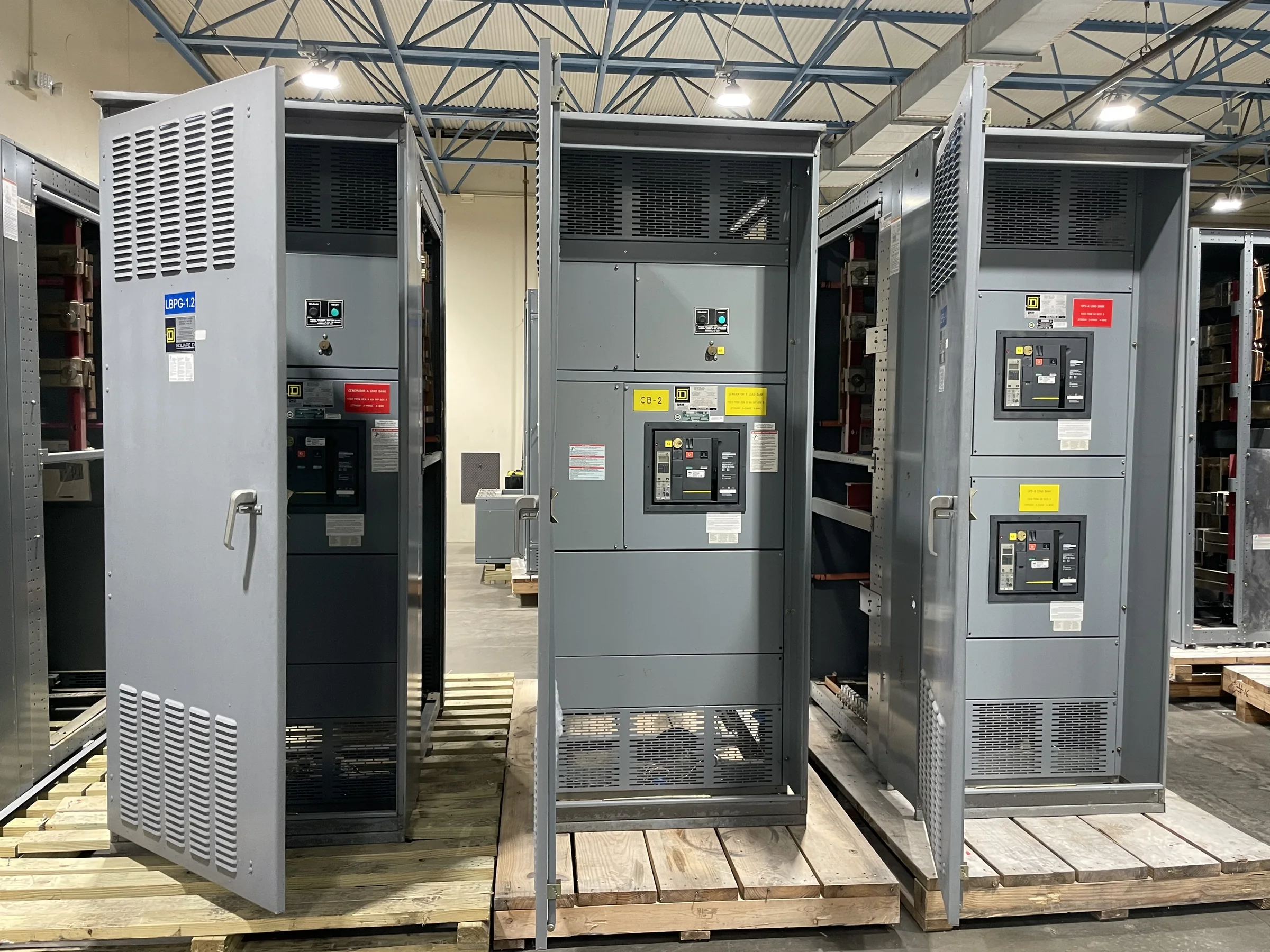
Define the Galveston Project Before Selecting a Switchboard
A switchboard that fits a Galveston facility starts with the electrical one-line diagram, the load served, and the conditions at the installation point—not a generic product name. Identify the service voltage, phase, frequency, available fault current, main and branch-device requirements, and whether the board will feed motors, HVAC, process equipment, tenant loads, or a mix. These details influence bus and protective-device selection, compartment arrangement, and the space needed for cable access. Ask the design team to confirm the governing project standards and the intended low-voltage switchboard application; UL 891 applies to appropriately evaluated low-voltage assemblies, not all distribution equipment. Share the latest drawings and load information when requesting a quote so the proposed configuration can be reviewed against the actual scope.
Account for Coastal Conditions and the Electrical Room
Galveston’s coastal setting makes the equipment environment a meaningful design input. Salt-laden air, humidity, wind-driven rain, and the possibility of water intrusion can affect enclosure selection, room ventilation, corrosion-control expectations, and maintenance planning. Describe whether the switchboard will be indoors or outdoors, the enclosure location, any exposure to washdown or corrosive process conditions, and the site’s temperature and humidity range. If the electrical room is near grade or in a flood-prone area, coordinate elevation and protection requirements with the facility’s design criteria rather than assuming a standard installation will suffice. These conditions can change materials, finish, enclosure details, and access needs. Confirm project-specific requirements with the engineer and manufacturer before releasing drawings; environmental suitability is not established by location alone.


Coordinate Ratings, Protection, and Connected Loads
Selecting protective devices requires more than matching the switchboard’s nominal voltage to the service. The engineer should establish available fault current at the equipment, required interrupting ratings, system grounding, and the coordination approach for upstream and downstream devices. Motor starting, transformer inrush, generator operation, and future load additions can all affect device selection or settings. A mismatch may compromise protection, create nuisance trips, or complicate selective coordination. Provide the latest utility or study data, transformer information, generator and transfer-switch details, and a load schedule when available. Confirm which party supplies and verifies settings, studies, and field acceptance. Final ratings and protection choices are project-specific; they should be documented and reviewed by qualified electrical professionals against the applicable design requirements, not inferred from a product description.
Review Drawings, Interfaces, and Replacement Constraints
Before approval, compare the proposed arrangement with the electrical room and the equipment it must connect to. Check lineup dimensions, working and access clearances, cable-entry direction, conductor bending space, bus connections, grounding provisions, and the location of feeder conduits. For replacement work, document the existing switchboard’s nameplate information, dimensions, incoming and outgoing connections, and any site restrictions that affect removal and installation. A replacement may require changes to conduit, cable, protective devices, or upstream equipment; physical fit alone does not establish electrical compatibility. Review submittal drawings with the engineer, installer, and facility representative, and resolve interface questions before fabrication. Clarify which items are included in the manufacturer’s scope and which are supplied or completed by others, so procurement and field teams can plan around the same approved configuration.
Plan Timing Around Submittals and Site Readiness
A useful schedule accounts for engineering review, drawing approval, fabrication, shipping, and the site’s readiness to receive and install the equipment. Share required-on-site dates, approval milestones, outage windows, and any procurement constraints when discussing timing with the manufacturer. Short lead times may be available for some custom builds, but configuration, component selection, drawing revisions, and material availability affect each project; no delivery period should be treated as guaranteed until confirmed for the approved scope. Late changes to feeder counts, metering, control requirements, or enclosure details can prompt redraws and disrupt sequencing. Identify the decision-makers for submittal comments and consolidate feedback where possible. Ask for current schedule expectations and define how changes will be reviewed, recorded, and communicated before authorizing fabrication.
Coordinate Delivery and Commissioning in Galveston
Plan shipment to the actual receiving point, not simply to a Galveston-area mailing address. Confirm truck access, turning and unloading space, dock or grade-level conditions, lifting equipment, packaging protection, delivery hours, and who will inspect and accept the shipment. Coastal weather and site access restrictions can affect unloading plans, so establish a receiving contact and contingency procedure with the carrier and project team. Before the switchboard arrives, verify that the electrical room is complete, dry, accessible, and ready for placement, with foundations, conduits, and installation resources coordinated to approved drawings. Schedule installation, inspection, testing, and energization through qualified personnel and the facility’s safety procedures; electrical work must be performed de-energized unless a properly justified exception is authorized under applicable rules. Record approved documents, shipment condition, and closeout requirements for turnover.