Define the Texas City Distribution Scope
For a Texas City project, start by documenting what the new switchgear must serve, not by selecting a lineup from a catalog description. Identify incoming sources, voltage, phase, frequency, available fault current, grounding method, required bus capacity, and the loads that need to remain available during maintenance. Note whether the work supports a refinery, chemical-processing facility, warehouse, utility interface, or another application; each can impose different operating and coordination requirements. Include expansion plans and any loads that cannot tolerate an interruption. These details help the manufacturer assess a custom configuration and flag missing information before drawings advance. Final ratings and suitability depend on the project’s electrical study, applicable codes, and equipment evaluation—not on location or application labels alone.
Coordinate Protection, Metering, and Controls
Protection and control decisions can affect both equipment layout and the time needed for engineering review. Provide the current one-line diagram, protective-device information, coordination-study assumptions, metering requirements, and control schematics when requesting a quote. Specify whether the lineup must interface with existing relays, communications, interlocks, or supervisory systems, and identify the party responsible for confirming those interfaces. In an operating industrial facility, an incompatible trip circuit or communications protocol can delay commissioning even when the power connections fit. Manufacturer review can clarify what information is needed, but it does not replace the engineer’s responsibility to verify the protection scheme. Confirm settings, wiring, and functional requirements through approved project documents before fabrication, and resolve changes through documented drawing revisions.


Check Environmental and Enclosure Requirements
Texas City’s Gulf Coast setting makes environmental conditions a practical design input, especially where equipment may face humid air, salt exposure, wind-driven rain, or temperature extremes. Describe the actual installation environment rather than assuming that an indoor or outdoor designation answers every question. Include the room or pad location, enclosure exposure, ventilation or cooling constraints, condensation concerns, access restrictions, and any site-specific corrosion-control expectations. If the equipment will be near process areas, clarify applicable hazardous-location boundaries and the separation between electrical rooms and classified spaces; do not assume standard switchgear is suitable within a classified area. These details affect enclosure selection, materials, clearances, and installation planning. The final design and environmental suitability must be reviewed against the site conditions and applicable requirements.
Plan the Replacement and Installation Interface
Replacement work often turns on details that are easy to overlook in an early equipment request. Record the existing lineup’s dimensions, bus arrangement, cable entry and exit points, conductor sizes, termination orientation, and available working clearances. Provide photographs and verified field measurements when drawings are incomplete, and identify obstructions such as piping, overhead steel, doorways, floor openings, and adjacent energized equipment. A new custom assembly is not automatically a drop-in replacement; differences in footprint, connections, or protection can require engineering changes to the surrounding installation. Establish who will verify field conditions and who will prepare demolition, anchorage, grounding, and connection documents. All installation and replacement work requires appropriate planning and de-energized work practices, with the facility’s qualified personnel controlling isolation and safety procedures.
Build a Practical Submittal and Schedule
A useful schedule begins with a complete technical package and clearly assigned review steps. Ask what is needed for quotation, then submit the one-line diagram, equipment schedule, specifications, site constraints, and required options together where possible. Identify approval deadlines, drawing-review responsibilities, release-for-fabrication authority, inspection expectations, and any owner or engineer hold points. Custom builds and short lead times may be available, but timing depends on the final scope, component availability, engineering decisions, approvals, and production conditions; request a project-specific schedule rather than relying on a general promise. Track revisions in a single document register so the quoted configuration, approved drawings, and purchasing documents stay aligned. If requirements change, confirm the effect on design, price, and timing before authorizing the change.
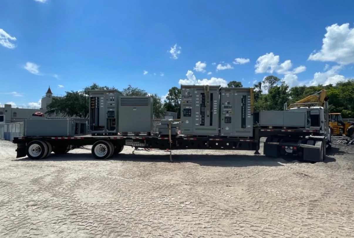
Coordinate Delivery Through the Texas City Site
Delivery planning matters because large electrical assemblies must reach the installation point without conflicting with site access rules or ongoing operations. Confirm the receiving address and contact, delivery windows, truck and trailer restrictions, unloading equipment, laydown space, weather protection, and the route from the gate to the electrical room or foundation. Texas City industrial sites may require advance driver onboarding, shipment documentation, escort arrangements, or coordination with plant traffic controls; establish the applicable requirements with the receiving facility rather than assuming standard delivery access. Agree on packaging, shipment sequence, and who will inspect and accept the equipment on arrival. Nationwide shipping can support the project, but the method and timing remain subject to the approved configuration and logistics plan. For low-voltage switchboard applications, discuss whether a UL 891-evaluated assembly is required; applicability is project-specific.