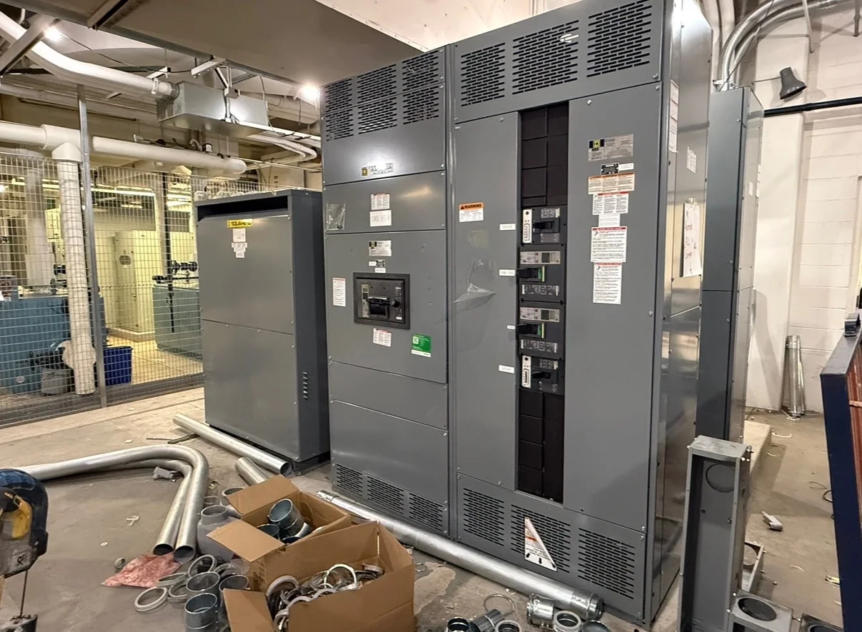
Plan the Power Path Around Data Hall Loads
Data center switchgear must fit the facility’s power architecture, not just a nominal voltage or ampere rating. Start with the one-line diagram and identify utility service, generator connections, transformers, bus ties, bypass paths, and downstream distribution. The operating sequence matters: a tie that is normally open, for example, may have different interlocking and control requirements from one used for routine transfer. Document normal and alternate sources, load priorities, available fault-current information, and the intended mode of operation. These details help the manufacturer evaluate an appropriate assembly and expose gaps before release. Ratings, configuration, and compatibility are project-specific; confirm them against the engineer’s design, utility requirements, and applicable codes rather than assuming a standard lineup will suit every data hall.
Coordinate Redundancy, Maintenance, and Future Capacity
Redundancy labels alone do not establish how equipment must perform during maintenance or a source outage. Clarify whether the project uses an N, N+1, or other arrangement, then show how each lineup, bus section, and tie supports the stated operating scenario. Identify which loads may be shed, whether maintenance can occur without interrupting critical service, and what transfer logic or operator actions are expected. Spare breaker provisions and future sections should be considered early: reserved space can affect lineup length, room layout, bus arrangement, and procurement scope. Avoid specifying unused capacity without a defined purpose, but do not leave planned expansion to field improvisation. Review the basis of design with the electrical engineer and manufacturer so the equipment configuration matches the intended resilience strategy.


Resolve Fault Duties, Protection, and Selectivity
Available fault current and protection coordination influence equipment selection, breaker application, and the consequences of a downstream fault. Provide the latest short-circuit and coordination studies when available, including utility and generator operating conditions that affect the calculation. Confirm protective-device types, trip functions, settings responsibilities, and any required zone-selective or differential protection with the project engineer. Selectivity goals should be stated clearly: a design may prioritize keeping unaffected data hall loads online, but the achievable coordination depends on the complete system and approved device combinations. Do not infer interrupting or withstand ratings from enclosure size or a similar prior installation. Final ratings, evaluated combinations, and applicable standards must be verified for the specific assembly and installation before approval.
Fit the Lineup to the Electrical Room and Site Route
A lineup that fits on a drawing can still be difficult to install if door openings, corridors, structural limits, or service clearances are overlooked. Share room plans, equipment elevations, access paths, floor loading criteria, and the planned method for moving sections from receiving to their final position. Confirm whether the design requires rear access, top or bottom cable entry, special separation from other equipment, or room for future extension. Cable bending space and the location of overhead bus or containment can constrain the lineup more than its footprint. These checks matter because late changes may require architectural revisions or field modifications. The project team should reconcile equipment dimensions and interface details with the latest coordinated drawings before approving manufacturing documents.
Make Procurement Timing and Delivery Requirements Explicit
Data center schedules often depend on equipment arriving in sequence with construction, utility work, and commissioning. When requesting a quote, provide the required approval and ship dates, delivery destination, receiving constraints, and whether the site can accept full lineups or needs sections coordinated with installation access. A U.S. manufacturer can discuss custom builds, American components, short lead times, and nationwide shipping, but timing and availability depend on the project’s design, material requirements, and current production conditions. Treat schedule dates as items to confirm in the quotation and order documents, not universal guarantees. Identify who will receive freight, inspect for transit damage, arrange unloading, and move equipment indoors. Clear responsibility prevents a scheduled shipment from becoming a site storage or installation problem.
Review Submittals, Interfaces, and Acceptance Planning
Before release, review drawings and submittals against the approved one-line, specifications, control diagrams, and room coordination model. Check device designations, metering, communications points, control power, terminal locations, cable access, labels, and the interfaces with generators, UPS systems, transformers, and building controls. Record deviations for formal approval instead of relying on assumptions carried over from an earlier project. For low-voltage switchboard assemblies, UL 891 may be relevant when the assembly is appropriately evaluated; it is not a blanket certification for every product or for medium- or high-voltage equipment. State the required standards and documentation in the project specifications, then confirm what applies to the quoted configuration. Agree on inspection, testing, shipping, and site acceptance responsibilities before procurement is complete.