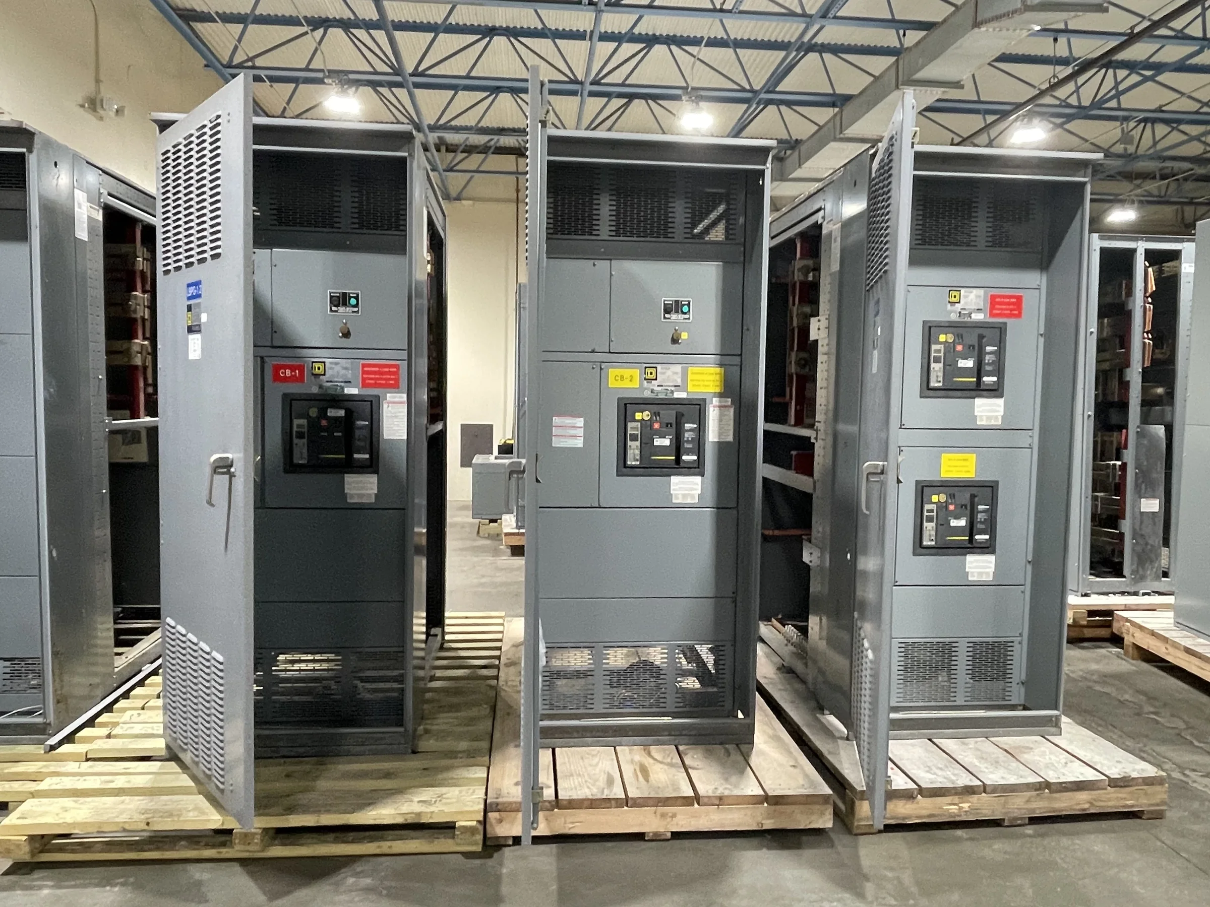
Specify the Busway for the Distribution Task
Start with the electrical duty, not a catalog label. Document system voltage, phase and conductor configuration, frequency, expected load, available fault current, and the protective-device arrangement feeding the run. These details help engineers evaluate busway capacity and short-circuit performance against the actual distribution system; selecting by current rating alone can leave important coordination questions unresolved. Identify whether the installation is intended for feeder distribution, plug-in access to loads, or a combination, since that affects the run layout and tap-off requirements. Note future load growth as a planning condition rather than assuming spare capacity is automatic. Final ratings, compatible components, and applicable standards depend on the project design and product evaluation. A complete basis of design gives the manufacturer something useful to review before quotation.
Map the Route, Connections, and Equipment Interfaces
A busway route is a three-dimensional installation, not just a line on a single-line diagram. Provide plan and elevation drawings that show direction changes, floor or wall penetrations, equipment locations, and the intended connection points. Include dimensions from reliable site references and identify conditions that could affect clearances, such as beams, piping, cable trays, and access panels. Confirm the arrangement at transformers, switchboards, panelboards, and other equipment with the responsible engineers; enclosure dimensions and connection orientation can determine whether a proposed transition fits. Flag expansion joints, seismic considerations, and building movement for design review where relevant. Missing a transition or misplacing a penetration can force field rework, disrupt other trades, and delay installation. Route review before release helps resolve interfaces while drawings can still be coordinated.


Check the Environment and Installation Conditions
The installation environment influences enclosure selection, connection details, and maintenance planning. Describe whether the busway will be indoors or outdoors, and note exposure to moisture, dust, corrosive agents, washdown, temperature extremes, or unusual vibration. A general location description is not enough when a production area, utility space, or exterior wall has distinct operating conditions. Ask the project team to confirm the required enclosure protection and any environmental limitations against the manufacturer’s documentation. Also establish whether the route passes through fire-rated construction and what sealing or firestopping responsibilities apply; these interfaces need coordination with the building design and approved materials. Installation access matters too: overhead work, restricted aisles, lifting limits, and nearby operating equipment can affect sequencing. Assessing these conditions early reduces the risk of specifying a system that is unsuitable for its actual setting.
Plan Tap-Offs, Loads, and Future Changes
For plug-in busway, map each intended tap-off location to the equipment it serves and the operating plan for that load. Verify how branch protection, disconnecting means, and tap-off units will be selected and coordinated with the upstream system; physical fit does not establish electrical compatibility. Record expected load characteristics, starting or inrush behavior where relevant, and any plans to add equipment later. The project engineer should determine whether the distribution arrangement supports those loads and whether spare tap positions or capacity are appropriate. Consider how operators and maintenance personnel will reach connection points without obstructing egress or interfering with production. If loads may move, distinguish relocatable connections from changes that require shutdown, inspection, or engineering review. Clear schedules help procurement quote the right components and help installers place outlets where they will be useful.
Prepare Drawings and Procurement Information
A useful quote package typically includes the one-line diagram, busway route drawings, load and tap-off schedule, equipment interface details, and stated electrical and environmental requirements. Identify project milestones, requested ship-to location, delivery constraints, and the date materials are needed on site, while treating timing as subject to scope review and availability rather than a guaranteed lead time. Ask which submittals are included and when coordinated drawings will be available for review. Resolve who is responsible for field measurements, final dimensions, penetrations, supports, and connection work before ordering. For low-voltage switchboard interfaces, UL 891 applies to appropriately evaluated switchboard assemblies; it is not a blanket certification for busway or medium- and high-voltage equipment. Confirm the applicable standards and product documentation for the exact configuration. Specific ratings, compatibility, evaluation, and availability remain project-dependent.
Coordinate Delivery, Installation, and Handover
Busway sections can be long, heavy, and sensitive to handling, so delivery planning is part of the installation plan. Confirm receiving hours, truck access, unloading equipment, staging space, indoor storage, and the sequence in which sections will be needed. Nationwide shipping can support projects across the United States, but the site team should verify route access and receiving arrangements for its location. Before shipment, align section identification and connection points with the approved layout so crews can match delivered material to the route. Installation and connection must follow the product instructions and project documents, with qualified personnel completing required de-energized work and inspections. At turnover, retain approved drawings, component and tap-off schedules, applicable evaluation documents, and maintenance information. An organized handover helps facilities staff trace the installed distribution path and plan future changes responsibly.