Distribution Planning for Port Operations
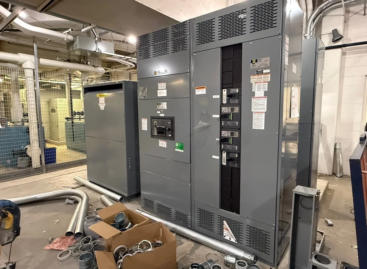
Port electrical systems serve a mix of steady facility loads and equipment that changes with vessel schedules, cargo activity, and terminal expansion. Start switchgear planning with an updated one-line diagram and a load list that distinguishes existing demand from proposed cranes, pumps, reefer connections, conveyors, workshops, and support buildings. That separation helps engineers evaluate feeder capacity, spare provisions, fault duty, and the effects of future additions without treating every load as identical. Confirm the available utility or on-site source characteristics and the required voltage, configuration, and protective-device coordination with the project team. A U.S. manufacturer can build new distribution equipment around the approved project requirements; final ratings, construction, and standards remain subject to engineering review and the equipment’s intended application.
Marine Exposure and Enclosure Decisions
Salt-laden air, wind-driven rain, humidity, dust, and washdown practices can shorten equipment life or complicate maintenance if the installation environment is misunderstood. Identify whether switchgear will sit indoors, in a conditioned electrical room, or in an exposed or semi-exposed location, and document temperature, moisture, corrosive contaminants, and cleaning methods. Those conditions inform enclosure selection, material and finish choices, ventilation, and any project-specific protective measures. Also consider how doors, cable entry points, and service clearances will be affected by the room layout and nearby piping or structural steel. Do not assume one enclosure arrangement suits every berth or terminal building. Review environmental requirements with the engineer and manufacturer before release, since suitability depends on the specified assembly and actual site conditions.


Power Continuity for Critical Terminal Loads
An interruption can affect more than the load directly connected to a failed feeder: cargo handling may pause, refrigerated containers may need attention, and restart sequences can place new demands on the system. Identify which loads require alternate sources, selective coordination, or a defined restoration priority, then show those relationships on the one-line diagram and sequence documentation. Where generators, utility services, or other sources are involved, engineers need confirmed source data and transfer-system requirements to assess the arrangement. Protection settings and available fault current must be evaluated as a coordinated system, not selected from a switchgear description alone. Clearly state any operational constraints, including permitted outage windows and temporary power plans, so procurement and engineering can align the new equipment with safe, maintainable continuity objectives.
Fit, Access, and Installation at the Terminal
At a busy port, the path from delivery point to electrical room can be as important as the switchgear footprint. Verify door and corridor dimensions, turning space, floor capacity, overhead obstructions, lifting access, and the location of existing services before approving the equipment arrangement. Shipping splits, where applicable, must be reviewed against the installation route and field assembly plan; they can affect rigging, alignment, and outage duration. Confirm working clearances, access for routine inspection, cable bending space, and room for future maintenance with the responsible electrical professional. Terminal traffic controls, security procedures, berth activity, and restricted delivery windows may also affect receiving and staging. Share these constraints early so drawings and delivery coordination reflect the site rather than assumptions.
Submittals, Standards, and Scope Alignment
A complete purchasing package reduces the risk of late changes caused by mismatched assumptions. Provide the latest one-line diagram, equipment schedule, load and feeder data, available fault-current information, protective-device requirements, control schematics, and applicable project specifications. Identify the required review drawings, wiring diagrams, component documentation, and closeout records, along with the parties responsible for approval. For low-voltage switchboard assemblies, specify whether UL 891 evaluation is required and confirm the applicable scope; it is not a blanket certification for medium- or high-voltage equipment. Clearly distinguish mandatory requirements from preferences, and flag interfaces with utilities, generators, transformers, and controls. The manufacturer can review the requested build against project documents, but ratings, standards compliance, and labeling must be confirmed for the particular assembly.
Schedule and Delivery Coordination
Procurement timing depends on the approved design, component availability, review cycles, and how quickly project decisions are resolved; avoid basing an outage plan on an assumed lead time. When requesting a quote, identify the desired ship date, required approval milestones, delivery location, unloading responsibility, and any restrictions on truck access or receiving hours. Include whether equipment will be staged, moved directly to an electrical room, or held for a later installation phase. U.S. manufacturing, American component options, custom builds, short lead times, and nationwide shipping are offerings to discuss against the specific scope, not guarantees for every configuration or schedule. Before release, reconcile the approved drawings, purchase documents, and site plan. Reconfirm shipment and receiving arrangements as the terminal’s construction and operations schedule develops.