Start With the Wastewater Process and Electrical One-Line
A wastewater facility’s switchgear should be specified against the loads and operating sequences it actually serves—not just the nominal plant capacity. Map influent pumping, screening, aeration, solids handling, disinfection, and any standby or reuse systems to the electrical one-line, noting which loads must remain available during a fault or maintenance outage. This reveals whether a proposed lineup needs separate sections, alternate sources, or provisions for future equipment. Motor starting methods, variable-frequency drives, harmonics, and load changes can affect distribution and protective-device coordination. Provide current and planned load lists, available fault-current information, voltage and frequency, and the one-line for review. Final ratings, construction, and protection settings depend on verified system data and the project’s engineering requirements.
Account for Moisture, Corrosion, and the Equipment Room
Wastewater buildings can expose electrical equipment to persistent humidity, condensation, washdown, corrosive gases, or airborne contaminants. These conditions can shorten component life or compromise insulation if enclosure construction, room controls, and maintenance practices are not considered together. Identify the installation location for each lineup: a conditioned electrical room, a process-area enclosure, or an outdoor structure. Share ambient temperature ranges, ventilation or dehumidification plans, exposure to chemicals, water-ingress risks, and the required enclosure characteristics. Also check access for front and rear service, working clearances, cable bending space, lifting paths, and doorway dimensions. A lineup that fits on a drawing may still be impossible to install or maintain if the room layout and cable routes are not coordinated early.


Coordinate Pumps, Drives, and Protective Devices
Pump stations and treatment processes often combine large motors, drives, control power, and equipment that must operate in a deliberate sequence. The switchgear design team needs enough information to evaluate feeder arrangements, device functions, metering, control interfaces, and coordination with upstream and downstream equipment. Submit motor schedules with horsepower, voltage, full-load current, starting method, drive details, and any expected operating combinations. Include generator or alternate-source data where applicable, because source characteristics can affect short-circuit calculations and protective-device selection. Confirm who is responsible for the system study, settings, and field verification; these are not interchangeable with a switchgear quotation. Reviewing these interfaces before release helps avoid late changes that disrupt controls integration, cable planning, or commissioning.
Define Resilience, Maintenance, and Future Expansion
An outage at a treatment facility can affect pumping, process continuity, and permit obligations, so resilience should be expressed as specific operating requirements. Identify essential loads, planned source transfers, maintenance isolation needs, and any redundancy philosophy established by the engineer or owner. Clarify whether operators need local metering, remote status points, alarm contacts, or communications with a plant control system, and provide the applicable control narratives and interface standards. Reserve capacity should be based on credible future loads and available room, not an arbitrary assumption that every section can be expanded later. Ask the manufacturer to review the proposed lineup boundaries, spare provisions, and physical expansion constraints. A documented approach supports maintainability while keeping the scope aligned with the facility’s actual operating plan.
Prepare a Complete RFQ and Review Submittals
A useful request for quotation includes the one-line, load schedule, equipment schedule, site conditions, preliminary layout, and the project’s required standards and documentation. State the requested scope clearly, including switchgear sections, breakers or switches, metering, control components, accessories, and any engineering or testing requirements. Identify required drawing formats, submittal milestones, approval responsibilities, and whether the quote must address spare devices or future provisions. During submittal review, compare the proposed lineup with the approved one-line, cable-entry plan, room clearances, and interface requirements; record exceptions rather than relying on verbal assumptions. For low-voltage switchboard assemblies, UL 891 may be relevant when specified and applicable to the evaluated assembly. Confirm project-specific listing and labeling expectations; it does not apply as a blanket certification to medium- or high-voltage equipment.
Plan Manufacturing Timing, Freight, and Site Readiness
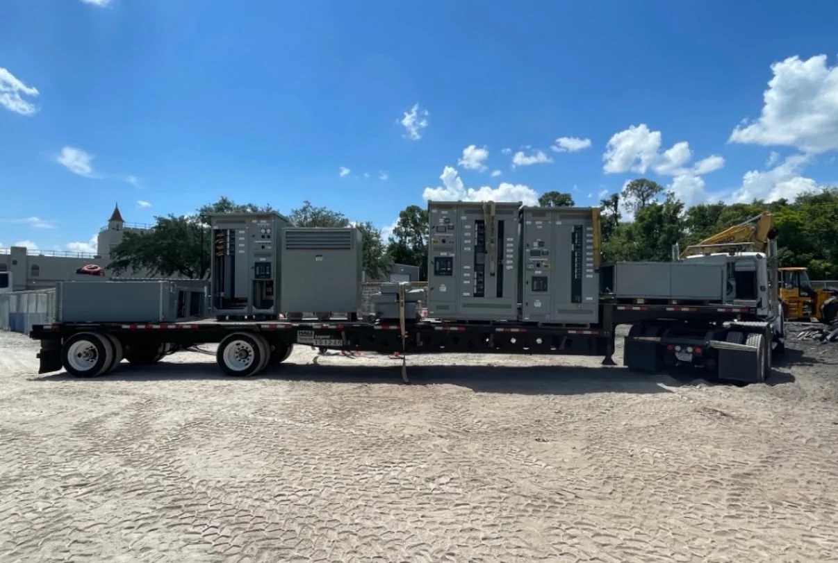
Production timing and delivery depend on the approved scope, component availability, drawing review, and release of required project information; confirm the current schedule for the specific order rather than relying on a generic lead-time estimate. Discuss schedule priorities early, especially when construction sequencing or an outage window limits when equipment can arrive. For nationwide shipment, provide the delivery address, receiving hours, unloading equipment, access restrictions, and whether the shipment must be coordinated with a general contractor or electrical contractor. Verify that the electrical room is dry, accessible, and ready before delivery, and confirm how sections will be moved from the receiving point to their final location. A U.S. manufacturer can discuss custom-built equipment, American components, and UL 891 assemblies where applicable; exact configuration, availability, and evaluation are project-specific.