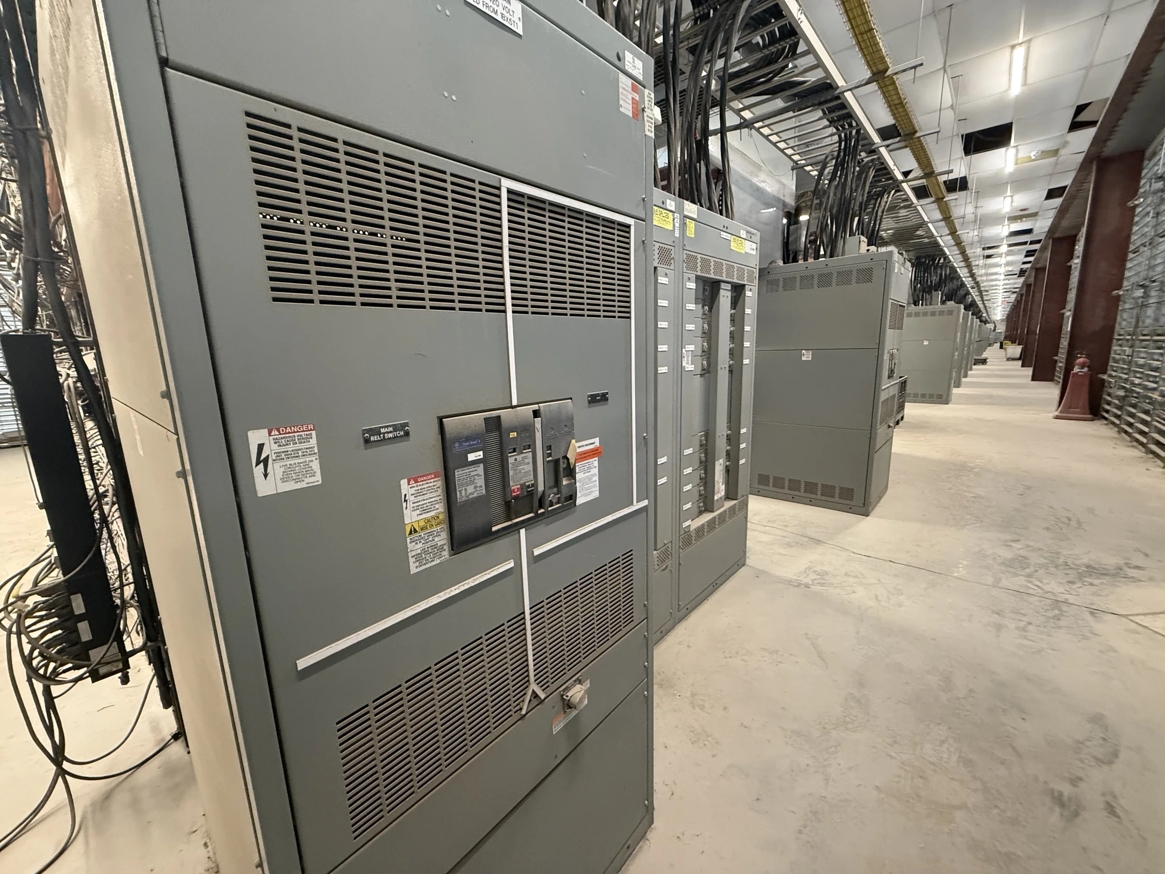
Define the Distribution Need Before Selecting Equipment
Start with the one-line diagram and the role the switchgear must perform: receive utility or generator power, distribute feeders, support a transfer scheme, or serve as a main distribution point. Record system voltage, phase and frequency, available fault current, grounding method, continuous load, and any expected motor or transformer inrush. These details shape the equipment configuration and help prevent a quote based only on an assumed ampere rating. Identify present loads as well as planned additions, but distinguish confirmed capacity needs from future possibilities. A manufacturer can use this information to develop a project-specific arrangement; final ratings and suitability depend on the electrical design and applicable evaluation. Clear inputs reduce late changes that can affect component selection, enclosure dimensions, coordination, and procurement.
Coordinate Protection, Metering, and System Interfaces
Protection and monitoring choices need to fit the wider electrical system, not just the switchgear lineup. Share the protective-device schedule, coordination or arc-flash study criteria, metering points, control-voltage requirements, and any communication or remote-operation interfaces available for the project. Confirm which devices and functions are required, who supplies them, and how field wiring will terminate. A mismatch between specified controls and installed interfaces can delay commissioning or leave operators without expected indication. Where the design includes utility, generator, or tie connections, document the operating sequence and interlocking requirements for engineering review. Do not assume a particular breaker, relay, trip unit, or network protocol is interchangeable. Device compatibility, protection settings, and configuration require project-specific confirmation by the responsible electrical professionals.


Match the Assembly to Its Standards and Intended Use
Specifications should state the equipment type, intended application, electrical ratings, construction requirements, and governing project standards clearly enough to distinguish a switchboard from medium-voltage or other switchgear. UL 891 applies to appropriately evaluated low-voltage switchboard assemblies; it is not a blanket certification for medium- or high-voltage equipment, and a standard reference alone does not establish that a particular assembly carries a UL label. Ask what evaluation or marking is required for the exact configuration and confirm it in the submittal process. Also identify enclosure and environmental conditions, access preferences, labeling, finish, and any seismic or other site-specific requirements. These choices affect design and acceptance. Applicable standards, ratings, and evaluation depend on the assembly and project; confirm them before purchase rather than assuming they are universal.
Resolve Room Layout, Access, and Installation Constraints
A lineup that meets electrical requirements can still create a site problem if it will not fit through the building route or allow safe access after installation. Provide room plans, equipment elevations, doorway and corridor clearances, floor-loading limits, cable-entry directions, and nearby obstructions for review. Identify working-space and egress requirements through the project design team, and verify how the equipment will be positioned, anchored, and connected. Cable bending space and top or bottom entry can influence section dimensions and internal arrangement, so late changes to conduit locations may require rework. Consider maintenance access, ventilation, housekeeping pads, and the path from receiving to the final location. Final dimensions and installation clearances must be checked against approved drawings, site conditions, and applicable codes before construction or delivery.
Build a Procurement Package That Supports Review
A useful request for quotation includes the latest one-line diagram, load and feeder schedules, equipment specifications, fault-current information, control schematics, room drawings, and a list of approved deviations or alternates. Mark open decisions plainly instead of allowing assumptions to become hidden requirements. Ask the manufacturer to identify information needed to complete engineering, describe the proposed scope, and provide drawings and documentation for the project review process. Compare proposals on included devices, bus and enclosure requirements, accessories, testing or documentation requested, exclusions, and interface responsibilities—not on headline price alone. Confirm who reviews and approves submittals and how revisions will be tracked. This discipline helps procurement, engineering, and construction teams spot scope gaps early; it does not replace the engineer’s responsibility to verify the design and approve the equipment.
Plan Timing, Shipping, and Site Readiness Together
Discuss schedule and delivery with the manufacturer while the specification and installation plan are still being developed. Custom configurations, component availability, drawing approvals, and design revisions can all influence the production sequence; request a project-specific schedule rather than relying on a general lead-time statement. Confirm the shipping destination, receiving hours, unloading equipment, delivery access, storage conditions, and the person authorized to accept the shipment. Long or heavy sections may need a planned route, staging area, or coordinated arrival with other trades. Nationwide shipping does not resolve site access or unloading responsibilities by itself. Before release, reconcile approved drawings, shipping configuration, and site readiness, then document any delivery constraints. Actual timing, configuration, and availability remain subject to project requirements and confirmation; avoid committing crews or shutdown windows until the relevant dates are agreed.