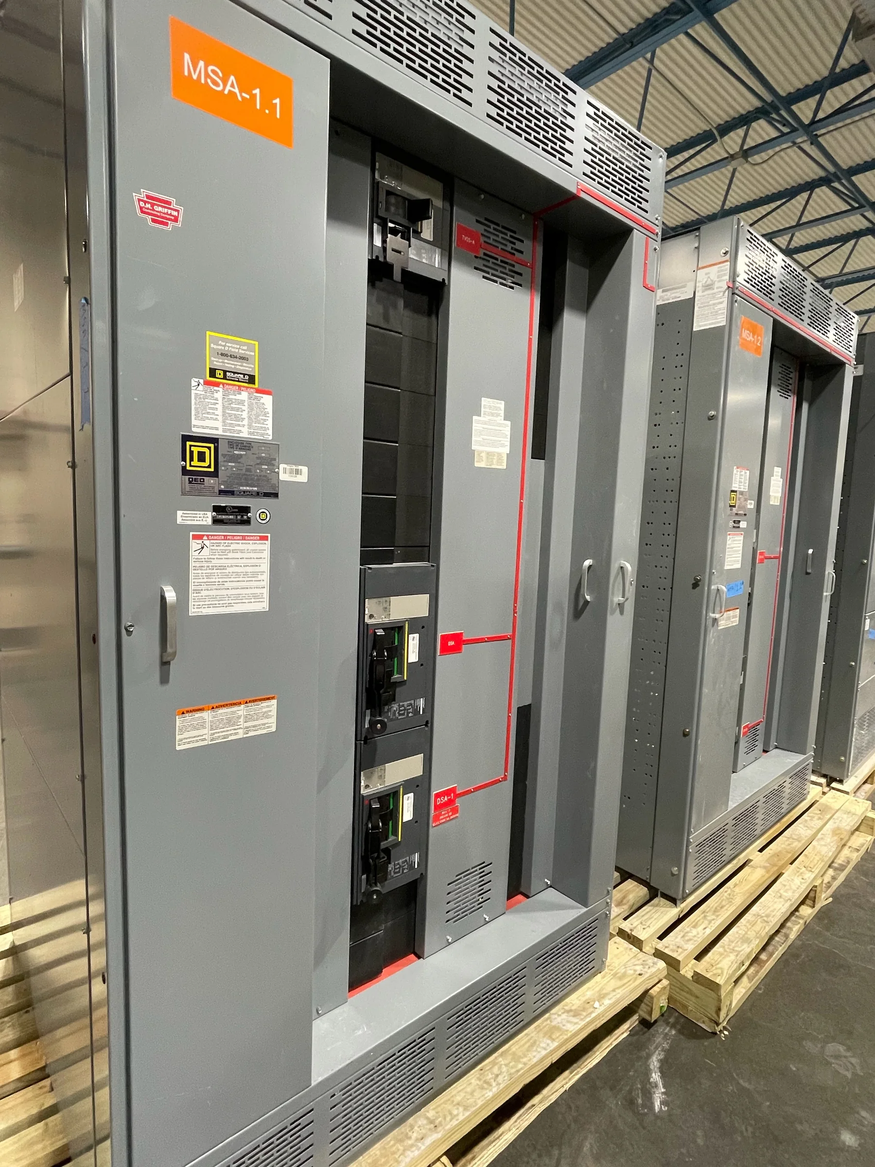
What Selective Coordination Means
Selective coordination is the deliberate arrangement of overcurrent protective devices so that, when a fault occurs, the device closest to the fault opens first while upstream devices remain closed. The goal is to limit an outage to the affected circuit or section rather than interrupting a larger portion of the facility. This depends on how breakers or fuses respond to fault current over time, not simply on choosing devices with different ampere ratings. Engineers evaluate the available fault current, protective-device characteristics, and the system configuration to determine whether devices coordinate across the conditions that apply to the project. Coordination is therefore a documented design outcome for a defined electrical system—not a general property of a switchboard or a guarantee that every fault will be isolated locally.
How Engineers Evaluate Device Coordination
An engineer typically compares time-current characteristics for upstream and downstream protective devices, considering both overload and short-circuit regions. The comparison must reflect the actual devices, trip-unit settings, current-limiting behavior where applicable, and available fault current at each relevant point. A chart that appears separated at one current may overlap at another, so reviewing only a single operating point can miss a coordination problem. Selective coordination may also involve time delays that affect how long equipment experiences fault current; that tradeoff must be assessed alongside equipment withstand capability and the project’s protection objectives. For procurement, this means the equipment schedule and one-line diagram should identify intended device types and system relationships early enough for engineering review. Final coordination depends on verified project data and selected equipment.


Why System Data and Fault Current Matter
Reliable coordination analysis begins with reliable system inputs. The engineer needs the source and transformer information, conductor lengths and sizes, grounding arrangement, generator or alternate-source details, and the operating configurations that could change fault current. A facility with a utility source and standby generation, for example, may have different available fault current depending on which source is serving the load. If the study assumes a configuration that does not match field conditions, its conclusions may not describe actual protective-device behavior. Procurement teams can reduce late revisions by confirming the latest one-line diagram, service data, and equipment interfaces before releasing a switchgear package for design. Missing information should be recorded as an open item, not silently replaced with an assumed value that could affect selection or coordination.
Coordinate Protection Without Overlooking Safety
Selective coordination supports continuity, but it is not the only protection objective. Increasing time delay or adjusting trip settings to keep upstream devices closed can increase the duration of a fault and may affect arc-flash exposure, equipment duty, or conductor protection. Engineers must assess these competing requirements together and document the basis for settings and device selection. Coordination does not mean that personnel should work on energized equipment, nor does it remove the need for appropriate electrical safety procedures, maintenance, or system studies. During design review, ask which operating cases were analyzed, whether protective settings are field-adjustable, and how approved settings will be communicated to commissioning and maintenance teams. A clear division of responsibility among the engineer, equipment supplier, installer, and owner helps prevent an approved design from being undermined by undocumented field changes.
Specify Equipment and Documents for Review
A useful equipment specification gives bidders enough information to respond consistently without presuming that one device arrangement fits every project. Include the system voltage and configuration, required bus and feeder arrangement, source conditions, protective-device preferences or performance requirements, and the documents expected for coordination review. The project engineer should define the analysis scope and acceptance criteria; the manufacturer can then develop equipment around the approved requirements and provide relevant submittal information for review. For low-voltage switchboard assemblies, UL 891 may be applicable when the assembly is appropriately evaluated, but it is not a blanket designation for every product or voltage class. Confirm the exact construction, evaluation, and project requirements in the submittal. Device substitutions, revised settings, or changes to the source configuration should be reviewed before approval because they can change coordination results.
Plan Review, Build, and Delivery as One Process
Timing is easier to manage when coordination inputs and submittal reviews are treated as part of equipment planning, rather than as tasks left until installation. Establish who will provide utility and generator data, who prepares and approves the study, and when device information must be finalized for the equipment design. The U.S. manufacturer can discuss project specifications, custom-build requirements, component preferences, and delivery coordination, but availability and schedule depend on the approved scope and project conditions. Nationwide shipping also makes practical receiving details important: confirm the delivery location, access restrictions, unloading responsibility, staging space, and the sequence for moving equipment into the electrical room. These details matter because a completed assembly may be difficult to store or reposition if the site is not ready. Keep approved drawings, study assumptions, device settings, and change records available for commissioning and future maintenance.