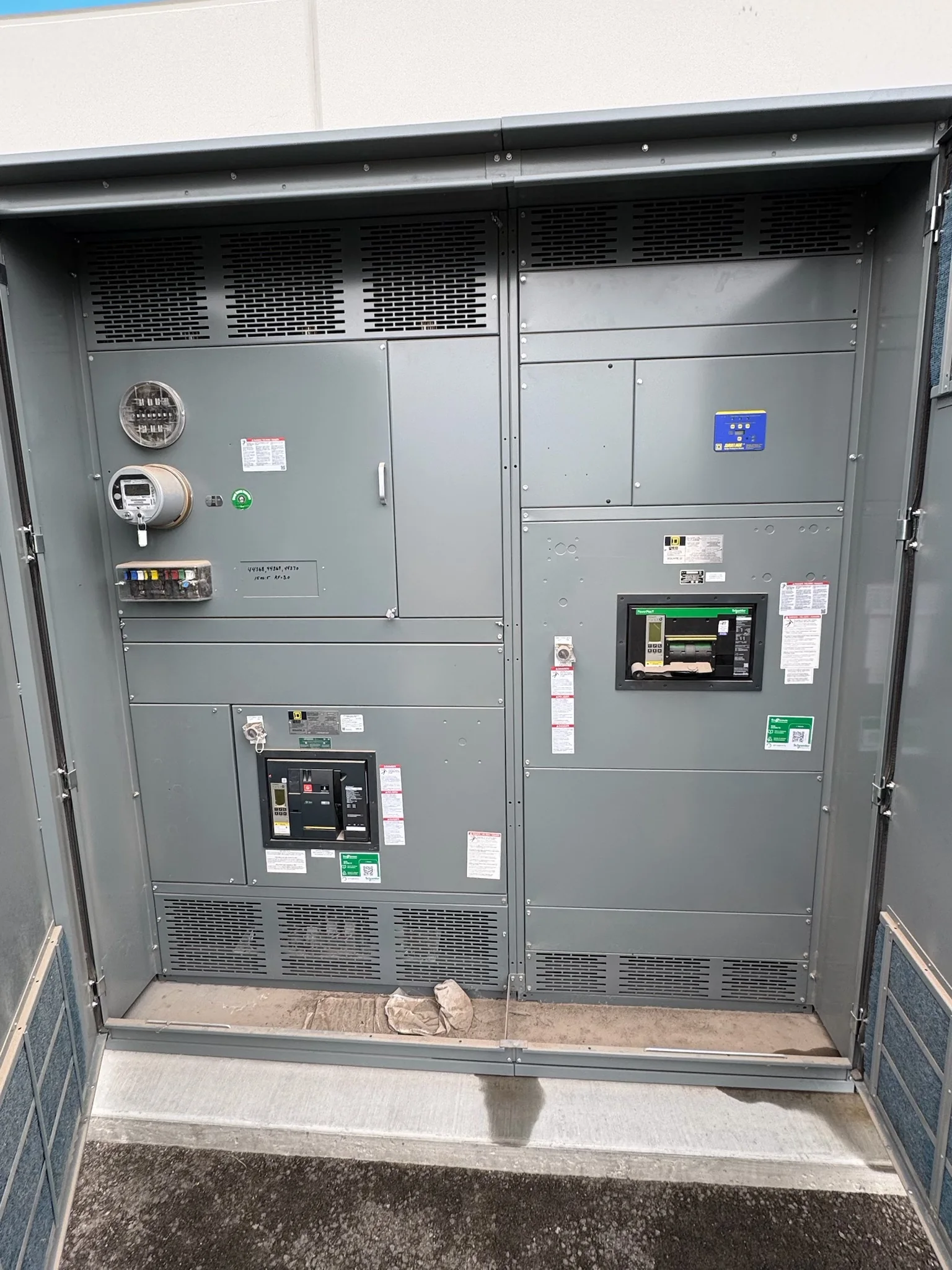
Define the Motor Control Center’s Role in the System
Start with the loads and operating sequence, not a preferred lineup or catalog description. Document each motor’s nameplate data, starting method, duty cycle, control voltage, required protection, and whether it must continue operating during a process interruption. Identify which loads are essential, which may start together, and whether operators need local control, remote commands, or both. Those details affect bucket arrangements, feeder capacity, control interfaces, and the amount of usable space needed for future changes. For a Katy facility, include the surrounding distribution system and actual process conditions—such as continuous production, pumps, compressors, or material handling—rather than assuming that similar equipment has identical requirements. A complete load schedule gives the manufacturer a practical basis for developing a project-specific configuration.
Resolve Electrical Ratings and Interface Requirements Early
A motor control center must coordinate with the electrical system it serves, so provide the available voltage, phase, frequency, grounding arrangement, and available fault-current information when requesting a proposal. The engineer of record should establish the required short-circuit rating and verify that protective devices coordinate with upstream equipment and connected motor loads. Clarify whether the scope includes incoming mains, transformers, power-factor equipment, communications, or only motor starters; these choices affect lineup dimensions and interfaces. Existing drawings can help, but they should be checked against field conditions and current studies before they become a purchasing basis. Ratings, device selection, and compatibility are project-specific, not assumptions to carry over from a previous installation. Resolve open questions before release for manufacture to reduce redesign and schedule disruption.


Choose Starters, Drives, and Controls Around the Process
Select each unit according to how the motor starts and how the process needs to respond. Across-the-line starters, reduced-voltage methods, and variable-frequency drives serve different operating needs; the appropriate option depends on motor characteristics, starting frequency, acceleration requirements, utility limitations, and the driven equipment. Drives may require attention to heat dissipation, cable length, harmonics, bypass needs, and separation from sensitive controls. Specify the intended control philosophy as well: local or remote operation, permissives, interlocks, status points, communications protocol, and alarm behavior. For a facility with multiple production areas, clear device tags and consistent control conventions can make troubleshooting and operator training more manageable. Confirm that proposed components and interfaces fit the application and project documents; do not assume a starter or drive is suitable solely because its horsepower appears adequate.
Check Katy Site Conditions and Delivery Access
A lineup’s shipping dimensions and handling requirements should be checked against the receiving route before the order is finalized. In Katy, coordinate the delivery point with the project’s actual site access, including gate hours, truck restrictions, construction traffic, unloading equipment, and the route from the receiving area to the electrical room. Confirm door openings, corridors, turning clearance, floor capacity, and any elevation changes with the installation team. Gulf Coast heat and humidity make storage planning important: protect equipment from moisture, condensation, dust, and construction debris, and follow the manufacturer’s storage and handling instructions. If the assembly must be split for transport or installed in stages, establish those constraints early because section arrangement, field connections, and the lifting plan can affect installation effort. Delivery dates remain subject to project-specific confirmation.
Make the Purchase Package Complete Before Release
A clear request for quotation helps procurement compare equivalent scopes rather than headline prices. Include the one-line diagram, load schedule, equipment location, required ratings, control schematics or sequence narrative, preferred components, communication requirements, and any applicable project specifications. Mark which documents are preliminary and identify the engineer responsible for resolving discrepancies. Ask the manufacturer to identify exceptions, required customer-furnished information, and assumptions that affect configuration or price. Confirm what drawings will be submitted for review, how comments will be handled, and which documents are needed for installation and commissioning. Specify any required assembly evaluation or labeling in the project documents; UL 891 applies to appropriately evaluated low-voltage switchboard assemblies and is not a blanket certification for motor control centers or higher-voltage equipment. Final applicability must be verified for the exact assembly.
Coordinate Schedule, Installation, and Commissioning
Discuss timing with the manufacturer using the project’s real decision and site dates: approved drawings, component selections, release authorization, delivery access, and the planned installation window. Custom construction and American-component preferences can shape procurement, but no delivery interval should be treated as guaranteed until the exact scope and availability are confirmed. Assign owners for utility data, drawing approval, site readiness, receiving, and installation so unanswered questions do not accumulate near shipment. Before arrival, verify that the electrical room is ready and that storage conditions are suitable. Installation and commissioning should follow approved project documents and applicable procedures, with required de-energized work, qualified personnel, and coordination among the electrical contractor, controls team, and facility operators. Record final settings, labels, test documentation, and as-built changes so future maintenance teams can understand what was installed.