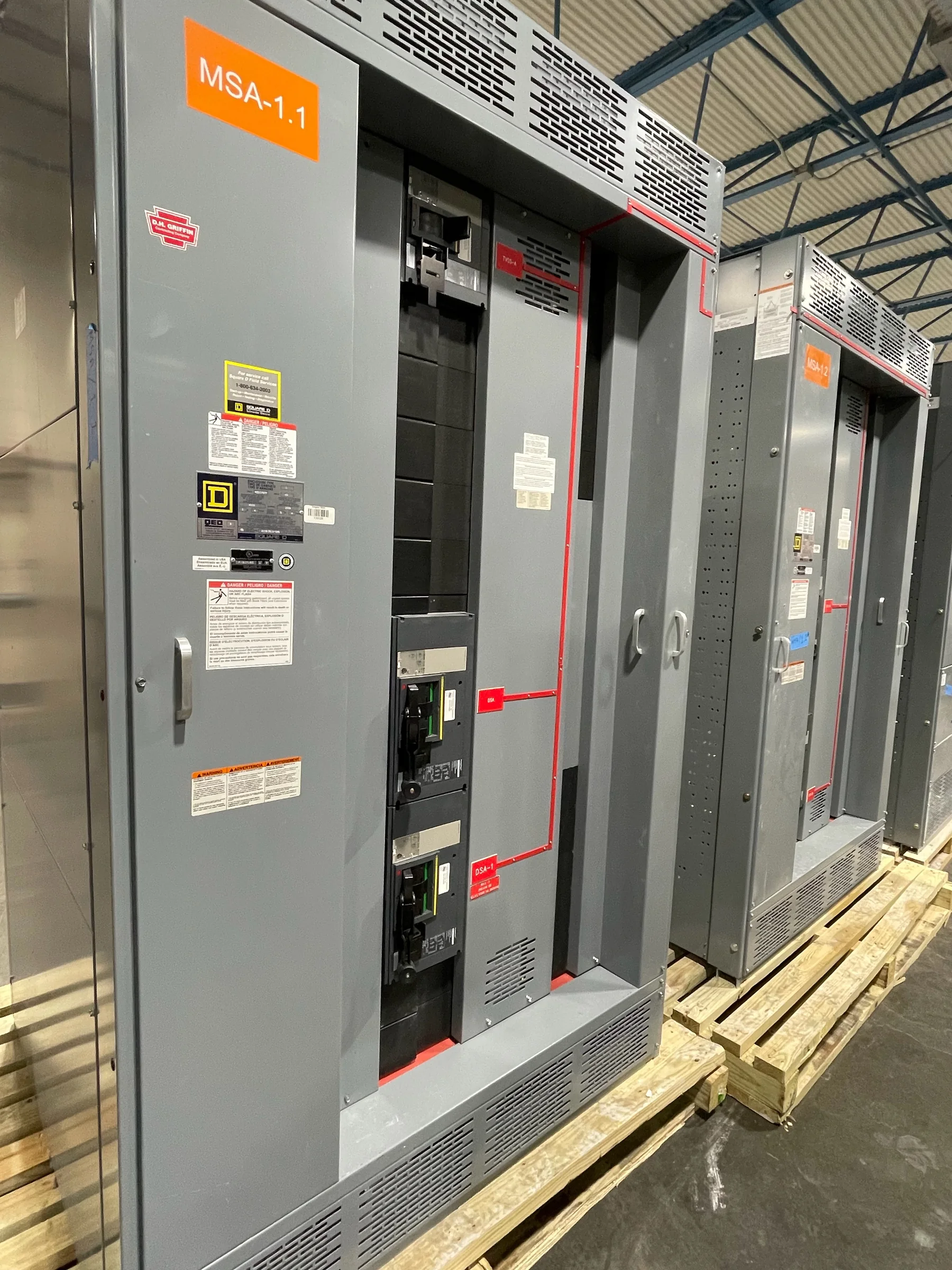
Define the Switchboard Around the Electrical Load
For a Katy facility, begin switchboard planning with the loads the equipment must serve, not a presumed standard configuration. Collect the one-line diagram, service characteristics, connected-load information, anticipated demand, and details about major motors, HVAC systems, process equipment, and future expansions. These inputs help the design team evaluate bus arrangement, feeder count, protective-device types, and available space within the assembly. They also reveal whether the project involves a new service, a building addition, or replacement of existing distribution equipment. A schedule that omits planned loads can leave too little capacity or require disruptive changes later. Have the engineer of record confirm design criteria and applicable requirements; final ratings, configuration, and suitability depend on project review and equipment evaluation.
Check Fault Duty, Coordination, and System Compatibility
A replacement switchboard must fit the electrical system, not merely the footprint of the equipment it replaces. Confirm available fault current at the point of connection, system voltage, phase and wire arrangement, grounding method, and the protective devices specified for the installation. Coordinate breaker functions and settings with the upstream and downstream devices so a fault can be isolated as intended; selectivity and protection depend on the actual system and engineering study. Existing drawings may not reflect utility changes, added transformers, or later equipment upgrades, so verify critical information before releasing a build. Document assumptions and identify any field verification needed. Short-circuit ratings, interrupting ratings, listing status, and compatibility require project-specific confirmation; no rating should be inferred from a product category or an old nameplate alone.


Resolve Layout, Access, and Environmental Conditions
Katy projects can involve new construction, occupied commercial buildings, warehouses, and industrial spaces, each with different installation constraints. Measure the intended location and document doorways, corridors, turns, ceiling height, floor openings, housekeeping pads, and the route from the unloading point to the equipment room. A switchboard that fits on a drawing may be impossible to move into place if access dimensions are overlooked. Record working-space requirements and nearby piping, ductwork, walls, and other obstructions for the project engineer to review. Also describe the installation environment, including indoor or outdoor placement, temperature exposure, moisture, dust, and corrosive conditions. Enclosure type and any special construction should be selected for verified site conditions and applicable requirements, not assumed from the city or building type.
Prepare a Complete, Reviewable Quote Package
A useful request for quotation gives the manufacturer enough information to identify scope and expose open decisions before fabrication. Include the latest one-line diagram, specifications, panel schedules, equipment schedule, preferred manufacturers or approved-equal rules, and any required submittal format. State the requested service characteristics, incoming and outgoing arrangements, metering needs, protective-device details, enclosure requirements, and known interface constraints. Mark items that are unresolved rather than filling gaps with guesses; a clearly flagged question is easier to review than an unstated assumption. For replacement work, provide photographs and legible nameplate information when available, but treat them as reference material rather than proof of system compatibility. The manufacturer can discuss a new custom build, while the engineer and owner confirm design intent, approvals, and project-specific requirements.
Coordinate Schedule, Submittals, and Delivery
Discuss timing early, because engineering review, drawing approval, component selection, fabrication, and transportation all affect the project schedule. A U.S. manufacturer may offer short lead times, but actual availability and delivery timing depend on the approved design, components, production requirements, and order details; request a project-specific schedule rather than relying on a general estimate. Assign responsibility for reviewing submittals and returning consolidated comments, since late or conflicting revisions can delay release. For delivery to a Katy site, confirm the receiving contact, site hours, truck access, unloading equipment, laydown area, weather protection, and restrictions on oversized loads. Coordinate shipment with the installation sequence so equipment is not left exposed or blocking active operations. Nationwide shipping is available as an offering, but route, handling, and delivery arrangements should be verified for the particular order.
Plan Replacement Work and Verify Documentation
When existing distribution equipment must be replaced, plan the transition as an engineered project with a defined outage and installation sequence. Document the existing source, downstream circuits, feeder destinations, controls, and any loads that cannot tolerate an interruption. Confirm who will approve switching plans, manage notifications, and verify the installation before energization; electrical work must be performed under appropriate safety procedures, with equipment de-energized when required. Compare proposed connection points and dimensions with verified field conditions, and resolve differences before equipment release. Request drawings and product documentation suited to the project review, including applicable ratings and evaluation information for the specific assembly. UL 891 applies to appropriately evaluated low-voltage switchboard assemblies; it is not a blanket certification for medium- or high-voltage equipment. Confirm required standards, labels, and acceptance criteria for each project.