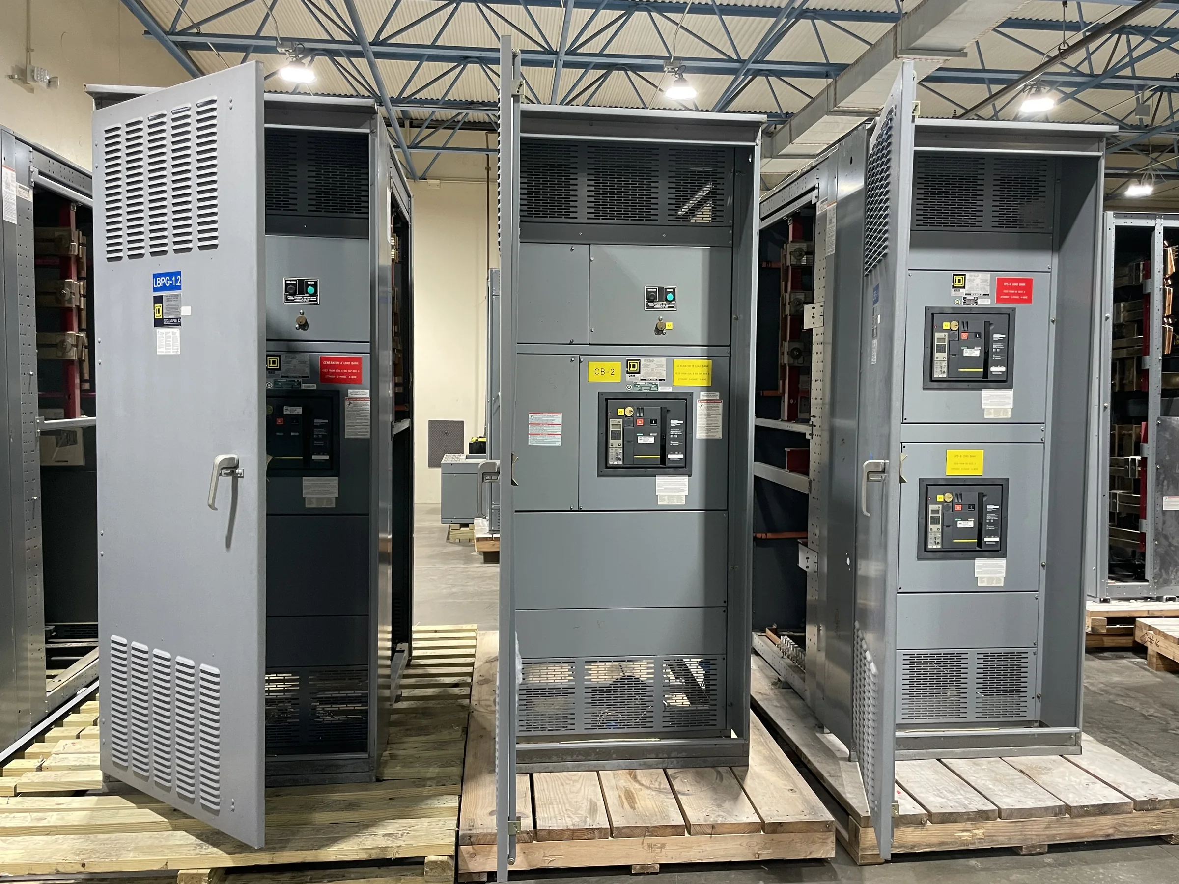
Specify the Switchboard Around the Distribution Plan
A switchboard should be specified from the facility’s electrical one-line diagram and operating needs, not selected by amperage alone. Confirm the service arrangement, system voltage, phase and wire configuration, available fault current, main and feeder requirements, and how the board will connect to upstream and downstream equipment. These details affect bus design, protective-device selection, compartment layout, and whether the proposed assembly can fit the intended application. Identify spare capacity and future feeder needs early; adding them later may require a different arrangement or more physical space. Requirements vary by project and must be checked against the applicable codes, utility criteria, and equipment interfaces. Provide the manufacturer with current drawings and clearly mark unresolved assumptions so they can be reviewed before a quote becomes a build specification.
Coordinate Protection, Metering, and System Interfaces
Protective devices and metering need to work as part of the complete distribution system. Share available fault-current information, upstream protective-device data, grounding approach, and any coordination or arc-flash study requirements with the design team and manufacturer. A breaker’s frame size alone does not establish its interrupting suitability, coordination, or compatibility with the intended assembly. Specify whether the project calls for electronic trip functions, ground-fault protection, utility or revenue metering, communications, or provisions for monitoring; verify each requirement against the chosen devices and control architecture. These decisions matter for safety, selectivity, operations, and commissioning, and may affect space, wiring, and documentation. Final settings and protection studies belong to qualified project professionals. Confirm interfaces with transformers, generators, transfer equipment, and building controls before approving submittals.


Check Room Access and Installation Conditions
A design that fits on paper can still be difficult to install if the electrical room, access route, or working space is overlooked. Confirm the available wall and floor area, required access and working clearances, door swings, overhead obstructions, floor loading, and the route from the receiving point to the final location. Note whether the assembly must pass through narrow doors, corridors, elevators, or areas with limited turning space. Section arrangement and shipping configuration should be reviewed against those constraints before release; late changes can affect both installation planning and equipment layout. Also coordinate cable entry, conduit locations, housekeeping pads, anchoring, ventilation, and environmental conditions. The electrical and construction teams should verify site dimensions and applicable requirements rather than relying on assumptions from an early floor plan.
Prepare Submittals and Approval Information
A complete purchasing package helps engineers evaluate the proposed switchboard before fabrication begins. Provide the latest one-line diagram, load and feeder schedules, site drawings, equipment interfaces, and project-specific specifications, then identify the documents required for review. Depending on the project, submittals may need arrangement drawings, device information, wiring diagrams, nameplate details, and confirmation of applicable standards or evaluation requirements. Review these materials for circuit identification, dimensions, access, cable landing space, metering, and control connections—not just overall appearance. Record deviations and open questions clearly, and route revisions to the responsible engineer for approval. This review matters because a small mismatch in feeder count or interface detail can delay procurement or require rework. UL 891 applies to appropriately evaluated low-voltage switchboard assemblies; it is not a blanket certification for all equipment.
Discuss Build Timing Before Releasing the Order
Schedule planning should begin while the design is still being coordinated. Ask for a project-specific estimate based on the actual configuration, required components, drawing review, approval cycle, and requested shipping arrangement; do not assume a standard lead time applies to a custom build. Confirm when the manufacturer needs approved submittals, final device selections, and any utility or consultant decisions to proceed. Long-lead components, specification changes, and incomplete information can influence the production sequence, so document the assumptions behind the estimate. Align the equipment delivery target with construction milestones, installation labor, outage planning, and any temporary-power strategy. A realistic schedule gives procurement and facilities teams time to manage dependencies without treating an unconfirmed date as a guarantee. Reconfirm timing when scope or approval dates change.
Coordinate Shipping, Receiving, and Replacement Work
Nationwide shipping does not remove the need for site-specific receiving and handling plans. Before dispatch, confirm the delivery address, receiving hours, unloading equipment, access restrictions, staging area, and who will inspect the shipment and report visible damage or shortages. Check the planned delivery method against the assembly’s dimensions and the site route, and determine whether sections must be moved or stored before installation. For a replacement project, document existing equipment interfaces, cable lengths and entry points, available outage windows, and the sequence for removing old gear and connecting the new board. Keep demolition, lifting, electrical connections, testing, and energization under qualified personnel and approved procedures; electrical work must be de-energized where required, not treated as optional. Resolve compatibility and site details before ordering, since field conditions may differ from legacy drawings.