Specify Equipment Around La Porte’s Operating Conditions
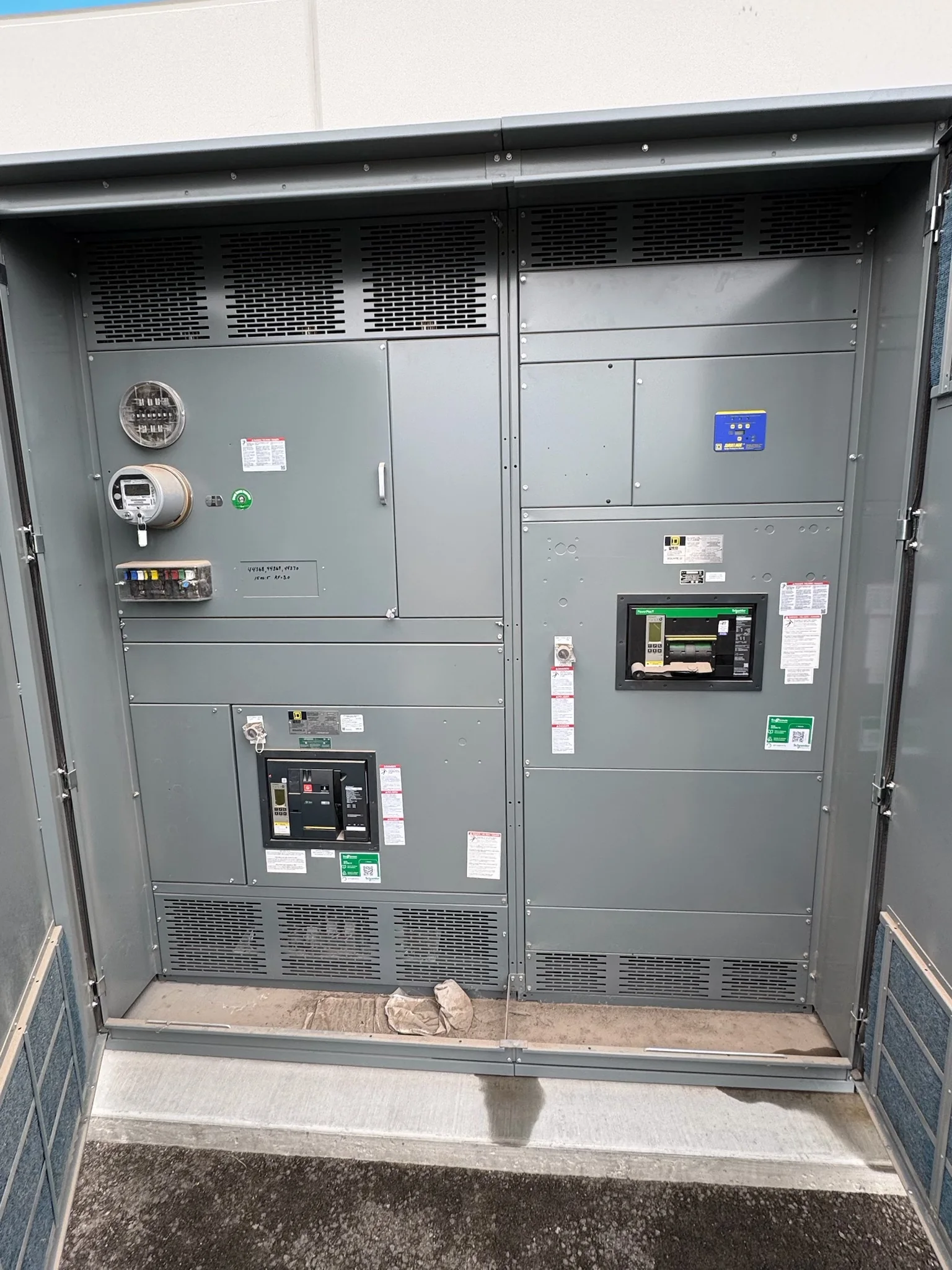
For a facility in La Porte, start switchgear planning with the electrical service, connected loads, and the conditions where the equipment will operate—not with a catalog label alone. An industrial site may include motor loads, process changes, outdoor exposure, or limited electrical-room space; each can affect the appropriate assembly, enclosure, and arrangement. Document the available fault-current information, system voltage, phase and wire configuration, continuous and peak loads, and any requirements for future capacity. These inputs help engineers evaluate ratings and protective-device coordination for the specific installation. Ambient temperature, moisture, corrosive contaminants, and ventilation also matter because they influence equipment suitability and maintenance needs. Confirming these conditions early reduces the risk of specifying equipment that fits a nominal rating but not the actual application.
Resolve Ratings, Protection, and Compatibility Before Quoting
A useful quote begins with enough system information to distinguish a replacement from a redesign. Share existing one-lines, available fault-current data, service and feeder requirements, breaker or fuse preferences, and coordination or arc-flash study criteria when available. The interrupting and short-circuit ratings must be evaluated against the installation’s calculated conditions; they should not be assumed from the old equipment nameplate alone. For replacement work, identify the existing manufacturer, model, dimensions, bus arrangement, connection points, and control interfaces, while treating compatibility as a project-specific engineering question. A changed utility source, transformer, or load profile can alter the required ratings. Review protection settings and selective coordination with the responsible engineer so that equipment selection supports the facility’s operating and safety objectives.


Plan Custom Construction Around the Actual Scope
Custom-built switchgear can address project-specific layouts and electrical requirements, but customization should follow a documented scope. Clarify the lineup arrangement, incoming and outgoing sections, metering, control power, communications, spare provisions, and any requested separation or access features. For a low-voltage switchboard, UL 891 may be relevant where the assembly is appropriately evaluated; it does not apply as a blanket certification to medium- or high-voltage equipment, and a particular listing should never be presumed. Identify applicable project specifications, drawings, and acceptance criteria before release for manufacture. A disciplined submittal review gives the owner, engineer, and contractor a chance to resolve conflicts between electrical intent and physical layout. That review is especially valuable when custom dimensions or interfaces must align with existing infrastructure.
Coordinate Delivery With La Porte Site Access
Delivery planning matters as much as equipment selection when a lineup must reach an operating facility near La Porte’s industrial and port-area corridors. A large assembly may require advance coordination for truck access, receiving hours, unloading equipment, route restrictions, security procedures, and temporary staging. Confirm the delivery address and site contact, but also verify door and gate clearances, turning space, floor capacity, and the path from unloading point to electrical room. Split shipment or section dimensions may affect handling and field assembly, so align those details with the project schedule and installation plan. Nationwide shipping does not remove site-specific logistics. Discussing access constraints before shipment helps reduce the chance that equipment arrives when the facility cannot safely receive, move, or protect it.
Use Submittals to Verify Fit and Installation Interfaces
Before approving fabrication, compare the proposed drawings and equipment schedule with the project’s electrical and architectural documents. Check lineup dimensions, section sequence, conduit or cable entry, working clearances, anchorage, bus connections, grounding provisions, and the location of field terminations. Confirm control wiring, metering, communications, and accessory requirements against the intended system, rather than relying on assumptions carried over from prior equipment. Where the assembly connects to existing gear, verify interface dimensions and electrical characteristics with current field information; older drawings may not reflect later modifications. Record open questions and obtain the responsible design professional’s resolution before construction release. Clear, coordinated submittals help prevent costly field changes, preserve access for operation and maintenance, and give the installation team a consistent reference for inspection and commissioning.
Discuss Timing, Replacement Strategy, and Safe Turnover
Request a project-specific schedule early, because engineering review, custom configuration, approvals, component availability, and shipping all affect the path to delivery. A U.S. manufacturer can discuss short-lead-time options where the project scope and availability support them, but no delivery period should be treated as guaranteed before confirmation. For a replacement, map the outage window, temporary power needs, demolition limits, lifting plan, and inspection sequence with the facility team and qualified electrical contractors. Switching and installation require an approved safety plan; equipment must be de-energized and verified before work, with applicable procedures followed by qualified personnel. At turnover, organize final drawings, device and setting records, test documentation required by the project, and maintenance information. A planned handoff supports safer operation and future troubleshooting.