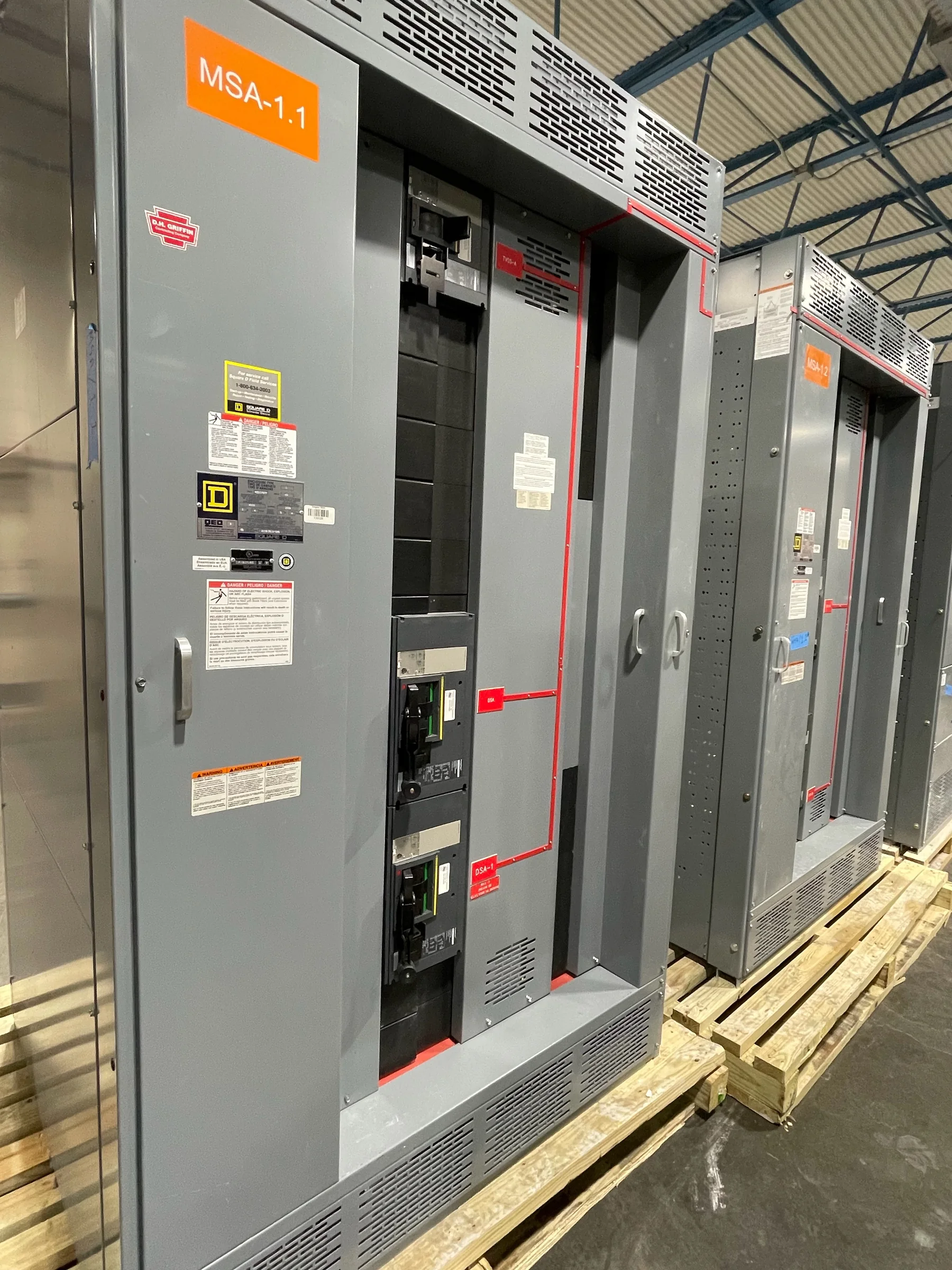
Define the Distribution Scope Before Selecting Equipment
For a Texas City project, begin with the electrical one-line diagram and the loads the equipment must serve, rather than a product label alone. Identify the source, nominal voltage, phase, frequency, available fault current, main and feeder requirements, and any planned ties or future expansion. These details determine whether a low-voltage switchboard, medium-voltage switchgear, or coordinated combination is appropriate. They also affect bus arrangement, protective-device selection, compartmentation, and the physical lineup. If existing equipment is being replaced, document its actual ratings and connections; matching the old nameplate without checking present system conditions can preserve a mismatch or overlook changed utility and load requirements. A U.S. manufacturer can build to a project-specific specification, but final design, ratings, and equipment applicability require engineering review.
Account for Texas City’s Industrial Environment
Equipment serving a Texas City facility may be exposed to Gulf Coast humidity, salt-laden air, heat, airborne process contaminants, or outdoor weather, depending on its location and enclosure. Those conditions can influence enclosure material and finish, ventilation, space-heating provisions, ingress protection, and maintenance access. They should be stated explicitly in the project specification instead of assumed from the city name. Confirm whether the lineup will be installed indoors, in a conditioned electrical room, or outdoors, and identify temperature, moisture, corrosive-agent, and site elevation conditions relevant to the design. Also check room clearances, working space, access doors, overhead obstructions, and cable-entry direction. Environmental choices matter because an enclosure or cooling approach suitable for a clean interior may not protect components or support serviceability in a harsher location.


Coordinate Protection, Interrupting Ratings, and System Studies
Protective devices must be considered as part of the electrical system, not selected solely by frame size or nominal current. Provide the current available fault-current study, source and transformer data, grounding method, and applicable coordination or arc-flash study information when requesting a proposal. The responsible engineer should verify interrupting and short-circuit ratings, device settings, selective coordination goals, and compatibility with upstream and downstream equipment. Changes in utility contribution, transformer impedance, or operating configuration can alter the required ratings. For a switchboard assembly specified to UL 891, confirm that the proposed low-voltage assembly’s evaluation and labeling match the project requirements; the standard is not a blanket certification for medium- or high-voltage gear. Study assumptions and approved protective-device details should be resolved before release, because late changes can affect layout, components, and review.
Resolve Interfaces With Existing Systems and Site Layout
Replacement and expansion work often turns on interfaces that are easy to miss in a preliminary equipment list. Record the existing lineup dimensions, bus and cable terminations, neutral and grounding arrangements, control wiring, metering signals, and required connection points. Confirm whether incoming and outgoing conductors enter from above or below, what bending space is available, and whether cable compartments can be reached after installation. Texas City facilities may have congested electrical rooms or process areas where access routes, nearby piping, and operating equipment constrain how a lineup can be positioned. Submit current drawings and clear photographs with field measurements, while treating them as information to verify—not a substitute for engineering. Resolving these interfaces early helps reduce installation rework and clarifies whether adapters, transition sections, or a different lineup arrangement are needed.
Make the Quote and Submittal Review Project-Specific
A useful request for quotation states the application, electrical ratings, one-line diagram, equipment arrangement, enclosure conditions, device schedule, metering and control needs, and required documentation. Include the project specification, preferred manufacturers or approved-equivalent rules, applicable standards, and any owner or utility requirements. Identify what must be supplied with the equipment, such as outline drawings, wiring diagrams, bills of material, and operation or maintenance information, as applicable to the scope. During submittal review, compare the offered configuration with the one-line and specification line by line; do not rely on a general description of “switchgear.” Flag exceptions, assumptions, and items requiring confirmation before approval. This process gives procurement, engineering, and the manufacturer a shared basis for evaluating cost and schedule without treating an unverified option as an accepted design.
Plan Schedule, Delivery, and Installation Readiness
Build the purchasing schedule around approved technical information, not an assumed standard production window. Custom configuration, component selection, drawing review, revisions, and customer approvals can all affect timing; request a project-specific schedule and identify decision dates that could influence it. For delivery to Texas City, coordinate the receiving location, unloading equipment, delivery access, shipment protection, and the site contact before dispatch. Check doorway and corridor clearances, turning space, floor loading, laydown area, and the planned move from the receiving point to the electrical room. Confirm packaging and handling requirements against the manufacturer’s instructions, and inspect the shipment for visible damage on arrival. Before installation or energization, qualified personnel should complete the required de-energized work, inspections, testing, and commissioning under approved project procedures; timing and responsibilities should be agreed in advance.