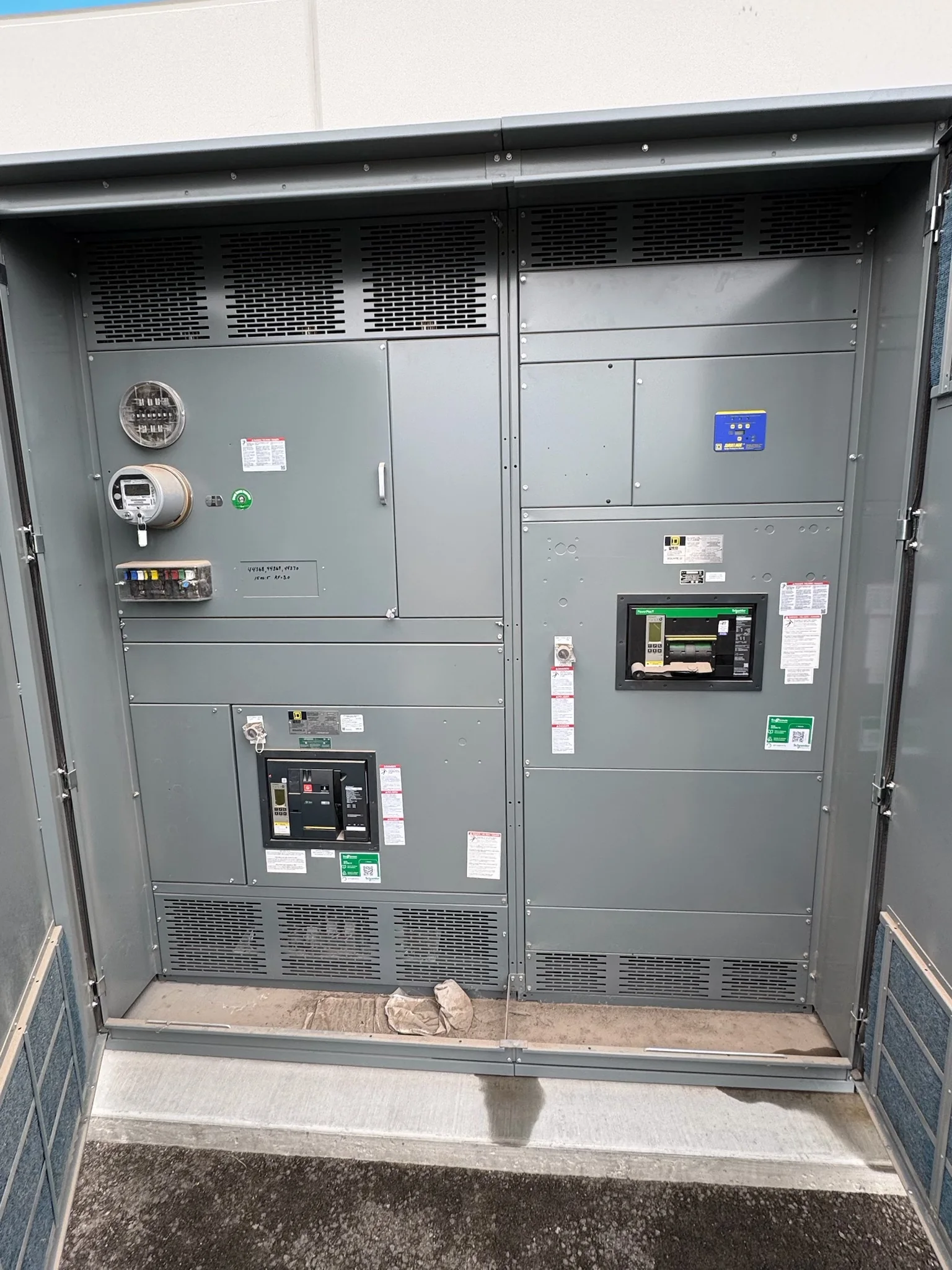
Define the Voltage Class and System Duty
Start the specification with the system’s actual voltage class, grounding arrangement, frequency, and operating duty—not simply the label “high voltage.” Equipment selection depends on the utility or plant one-line diagram, available fault current, protective-device coordination, and the way the switchgear connects to transformers, generators, motors, or incoming feeders. Confirm whether the project calls for metal-clad switchgear, another switchgear arrangement, or a different type of high-voltage equipment; these terms are not interchangeable. Interrupting and withstand requirements, insulation approach, bus configuration, and operating sequence must be evaluated together. An incorrect assumption can create a mismatch at the point of connection or complicate protection studies. Provide the latest one-line, utility data, and design basis so the manufacturer can identify questions before the equipment is finalized.
Match the Equipment to the Application
Application details shape the lineup just as much as voltage. A utility substation, industrial plant, campus, and renewable-energy interconnection may have different requirements for feeder count, bus arrangement, metering, controls, and future expansion. Describe what each circuit serves, how alternate sources operate, and whether the project needs provisions for tie breakers, spare cells, or remote status and control. If large motors or transformers are involved, include their starting or energization characteristics where available; these can affect protection and coordination decisions. Environmental conditions matter, too: indoor or outdoor installation, altitude, ambient temperature, contamination, moisture, and seismic criteria may affect equipment selection or enclosure requirements. Resolving these conditions early helps avoid late drawing changes and keeps the proposed assembly aligned with the system’s operating purpose.


Coordinate Protection, Controls, and Interfaces
Switchgear cannot be specified in isolation from its protection and control scheme. Identify the relay functions, instrument transformer requirements, trip and close circuits, control-power source, communications interfaces, and any required connection to a plant or utility control system. Confirm which party supplies relays, meters, wiring beyond the lineup, and settings; unclear scope boundaries can leave gaps during commissioning. Protection settings depend on the system study and must be reviewed by the responsible engineer, not assumed from a catalog description. Also document interlocking requirements and operating philosophy, especially where alternate sources or bus ties are present. A clear interface schedule gives the manufacturer and project team a shared basis for drawings, wiring, and review. Verify compatibility with existing equipment and protocols before approving the design.
Plan the Site, Access, and Installation
A technically suitable lineup can still be difficult to install if the room and delivery route are overlooked. Check equipment-room dimensions, clearances, floor loading, cable entry, grounding provisions, ventilation, and access for maintenance against the project drawings and the manufacturer’s proposed arrangement. Measure doorways, corridors, elevators, loading areas, and turning points; a lineup that must be moved in sections may require different coordination than one transported as an assembly. Consider crane access, rigging limits, weather exposure during unloading, and the sequence for placing sections. For replacement work, document existing foundations, bus or cable connections, and outage constraints, then plan the transition with qualified project personnel. These checks help surface civil, logistical, and shutdown conflicts before they affect installation.
Prepare a Reviewable Project Package
A useful request for quotation includes enough information to evaluate the equipment without treating preliminary data as final design approval. Provide the one-line diagram, equipment schedule, site conditions, applicable project specifications, preferred standards, and known utility requirements. State the required voltage class and system duty when established, but flag values still under study. Include requested drawings and submittals, such as general arrangement, elevations, elementary diagrams, wiring information, and equipment data, as applicable to the scope. Identify review milestones, responsible approvers, and any required coordination with the engineer of record or utility. A document register can also show which inputs remain outstanding. This disciplined package reduces ambiguity, supports meaningful technical review, and helps the manufacturer identify exclusions or assumptions that could otherwise surface after a purchase order.
Discuss Build Timing and Delivery Early
Discuss schedule and shipping during specification, because timing depends on the approved design, component availability, review cycles, and the project’s required configuration. Share the needed-on-site date, receiving hours, storage conditions, unloading capability, and any restrictions on truck or crane access. Nationwide shipping can support projects in varied locations, but the delivery plan still needs to match the site’s route, staging area, and installation sequence. Ask how drawing approvals, changes, and inspection requirements fit the proposed schedule; late revisions can affect both production and field readiness. Confirm packaging, shipment configuration, and responsibility for receiving inspection before release. The manufacturer can discuss a project-specific timeline and delivery approach, but no lead time or arrival date should be treated as guaranteed until scope, availability, and schedule are confirmed.