Define the Texas City Distribution Scope
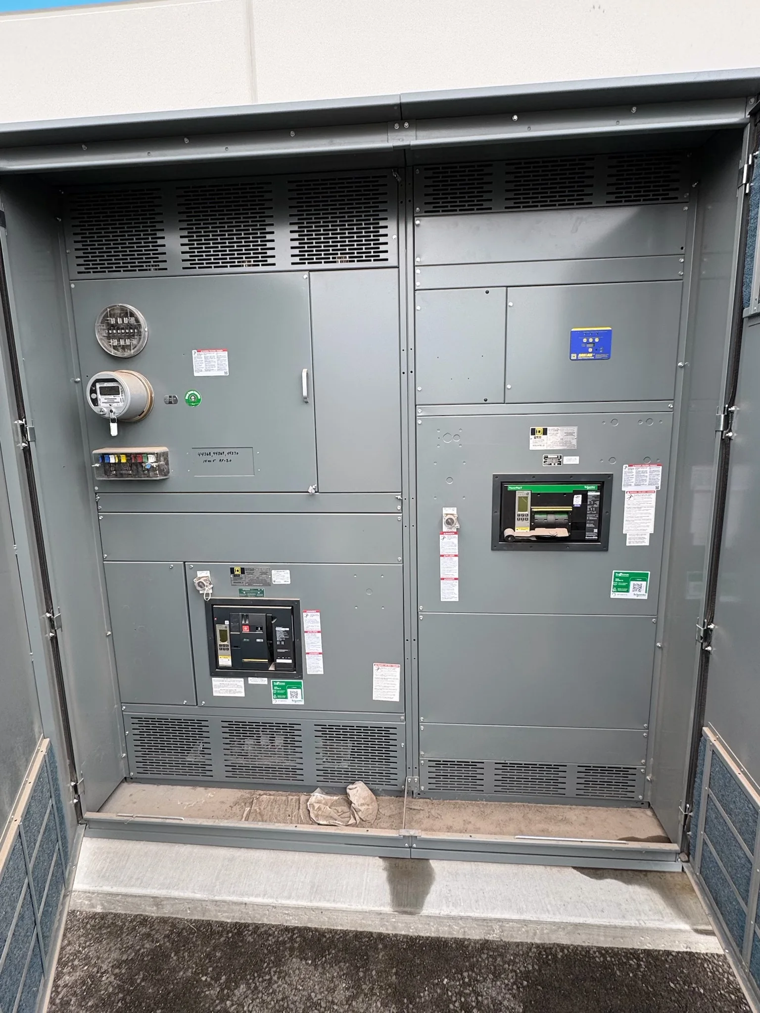
For a Texas City project, begin with the equipment’s role in the distribution system, not a catalog description. Confirm whether the scope is a new low-voltage switchgear lineup, a replacement section, or equipment coordinated with an existing service. Gather the one-line diagram, system voltage, available fault-current information, grounding arrangement, and intended source configuration. These details influence bus ratings, protective-device selection, section arrangement, and whether the proposed assembly can interface with upstream and downstream equipment. Texas City facilities may include industrial processes, utility infrastructure, warehouses, and commercial operations, each with different continuity and load-growth priorities. Identify critical loads, planned expansion, and operating constraints early; otherwise, a quote may omit required compartments, metering, or interfaces. Final ratings and compatibility depend on project-specific engineering review.
Resolve Ratings, Protection, and Coordination
Short-circuit withstand, continuous-current requirements, and protective-device coordination should be evaluated together. A switchgear rating cannot be selected responsibly from load alone: the engineer also needs the system’s available fault current, protective-device clearing characteristics, and the applicable design basis. Request the manufacturer’s review of the specified breaker types, trip functions, control power, metering, and any required communications so differences are visible before release. For a low-voltage switchboard assembly, UL 891 may be relevant when the assembly is evaluated for that standard; it should not be read as a blanket certification for every lineup or for medium-voltage equipment. Confirm the project’s required standard, labeling, and documentation in writing. These checks matter because an apparently minor device or bus change can affect the coordinated design.


Account for Site Conditions Near the Coast
Texas City’s Gulf Coast setting makes environmental review a practical part of equipment selection. Ask the project team to document the installation location, indoor or outdoor exposure, ambient conditions, ventilation, contaminants, and any washdown or corrosion-control requirements. Salt-laden air, moisture, and industrial pollutants can influence enclosure construction, finishes, heaters, or other protective provisions, but the right approach depends on actual exposure and the specified equipment design. Do not assume that a standard indoor lineup is suitable for a particular room or process area. Confirm the room’s clearances, access routes, floor condition, anchoring expectations, and cable-entry direction while layout is still flexible. Addressing these conditions before manufacturing helps avoid field modifications that can complicate installation, inspection, and maintenance.
Coordinate Replacement and Retrofit Interfaces
Replacement work often turns on details that a one-line diagram does not show. Before requesting a proposal, assemble available nameplate data, enclosure and section dimensions, bus information, breaker identification, cable sizes and termination locations, control schematics, and clear photographs. Record what must remain in service and which interfaces may change. A new lineup is not automatically a drop-in fit: footprint, bus connection, cable landing space, control wiring, and protection settings all require review against the existing installation. If the project is a retrofit, define the boundary between new equipment and retained gear, including who verifies field dimensions and compatibility. Plan outages and sequencing with the facility’s qualified electrical team. De-energization and safe work practices are essential; schedule pressure does not make energized installation work acceptable.
Review Drawings, Submittals, and Commercial Scope
A useful quotation process makes both technical assumptions and commercial boundaries explicit. Send the current one-line, equipment schedule, specifications, available fault-current and coordination information, general arrangement, control requirements, and preferred delivery destination. Identify requested options, project milestones, approval contacts, and whether installation, startup, or field services are part of the request rather than assuming they are included. Ask for a submittal package suited to the project’s review process, such as equipment layouts, ratings, device details, and connection information as applicable to the design. Resolve deviations in a written clarification log before approval. This is especially valuable when an engineer, owner, contractor, and purchasing group each control different decisions. Clear scope reduces the chance that an omitted feature or unresolved exception becomes a late change.
Plan Manufacturing Timing and Texas City Delivery
Discuss timing using the project’s actual approval and site-readiness milestones, not an assumed standard lead time. Custom builds and component availability can affect the schedule, while drawing review, comment resolution, and release for production also consume time. Ask the U.S. manufacturer to confirm current availability and the schedule basis for the quoted configuration; timing is project-specific and should not be treated as guaranteed until confirmed. For delivery to Texas City, coordinate the receiving address, site contact, unloading equipment, delivery-hour limits, access restrictions, staging space, and route from the gate to the electrical room. Large switchgear sections may require a planned handling sequence and protected storage. Confirm shipment configuration and receiving responsibilities early so transportation, construction progress, and installation planning remain aligned.