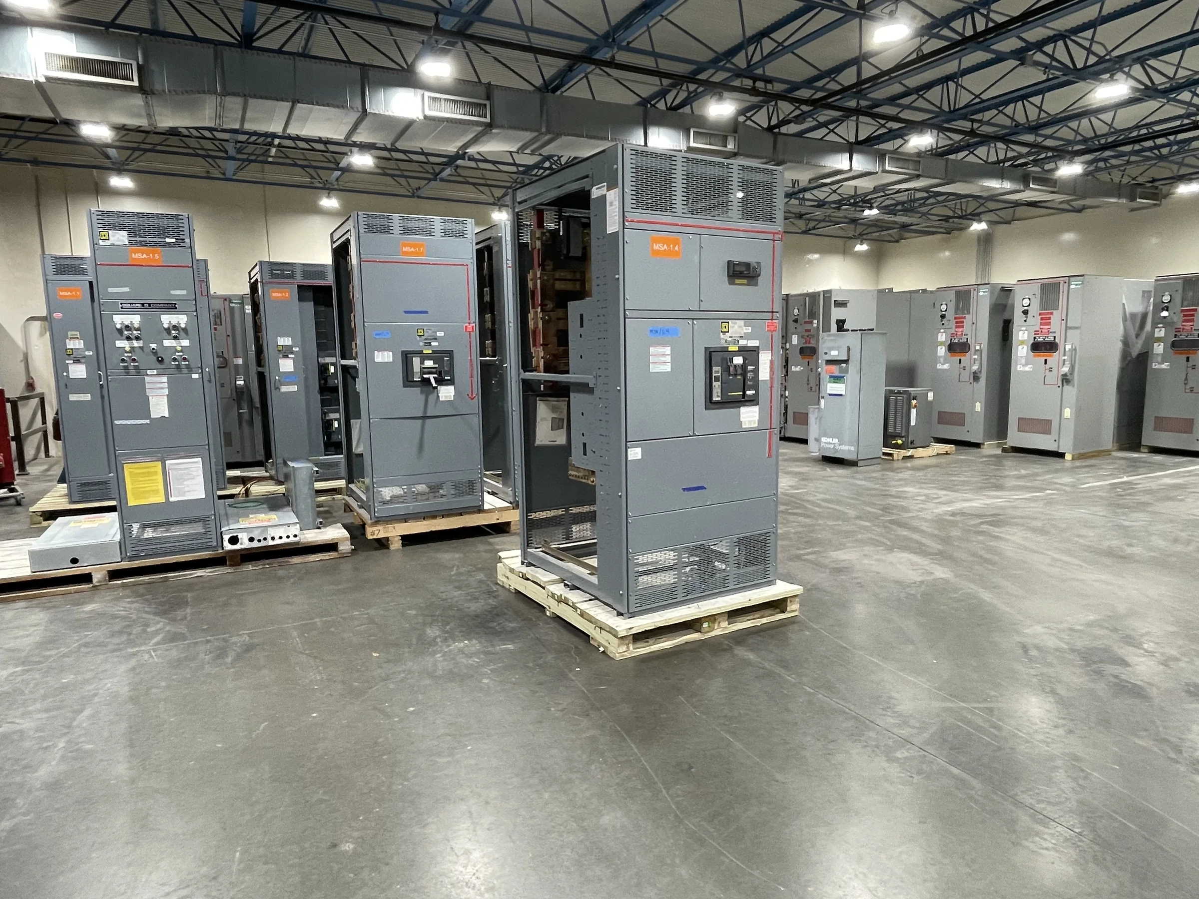
Define the Distribution Scope Before Selecting Equipment
Low-voltage switchgear is not specified by voltage class alone. Start with the one-line diagram, source configuration, connected loads, and the way the facility needs to isolate and distribute power. The arrangement may need to accommodate utility service, generators, transformers, bus ties, or separate sections for critical and noncritical loads; each choice affects lineup structure and coordination. Confirm system voltage, phase, frequency, available fault current, and the required continuous current ratings from project documents rather than assumptions. Identify future feeders and planned load growth early, because adding space or provisions later can be more disruptive than accounting for them in the initial design. A U.S. manufacturer can build around defined project requirements, but final ratings and configuration remain subject to engineering review.
Coordinate Protection, Interrupting Duties, and System Studies
Protection decisions must match the electrical system, not just the nameplate ratings of individual devices. The equipment selection should be checked against available fault current and the results of applicable short-circuit, coordination, and arc-flash studies. Those studies help establish whether protective devices can safely interrupt expected faults and whether upstream and downstream devices operate in a suitable sequence. If a service upgrade, transformer change, generator addition, or utility-source change is planned, request updated system data before equipment is released for manufacture. Otherwise, a lineup specified for earlier conditions may not suit the revised system. Provide the manufacturer with study assumptions and the required device types, trip functions, and accessories. Final compatibility, ratings, and protective settings are project-specific and should be confirmed by qualified engineering personnel.


Make the Lineup Fit the Electrical Room and Access Route
A lineup that fits its electrical ratings can still create a costly site problem if the room or delivery path is overlooked. Confirm room dimensions, ceiling height, door openings, floor loading, housekeeping pads, cable trenches, and required working clearances against the project layout and applicable codes. Review whether conductors enter from above or below, where pull space is needed, and how equipment doors, barriers, and removable sections affect access for operation and maintenance. The route from receiving area to final location matters too: turns, ramps, elevators, and restricted loading docks can limit how equipment is transported or positioned. Resolve handling and placement constraints before approving drawings. Accurate site information helps align the switchgear arrangement, shipping configuration, and installation plan without assuming that a standard footprint will work.
Review Drawings and Submittals Against the Purchase Scope
A detailed submittal review is an opportunity to catch mismatches before fabrication, when changes are generally easier to coordinate than after delivery. Compare the proposed lineup with the purchase specification, one-line diagram, equipment schedule, and interface requirements. Check section arrangement, feeder quantities, device functions, metering, control power, incoming and outgoing cable provisions, and any required communication interfaces. Confirm that specified accessories and labels are shown, and identify which items are by others, such as protective relays, cables, or field wiring. For low-voltage switchboard assemblies, UL 891 may be relevant when the application and evaluation support it; it is not a blanket designation for every assembly or equipment class. Ask for clarification wherever documents conflict, and confirm applicable standards, evaluation, and labeling for the specific supplied equipment.
Plan Procurement Timing Around Design and Site Readiness
Lead time depends on the agreed configuration, component availability, drawing approvals, and the state of the project when the order is placed. Custom requirements, late revisions, or incomplete source information can add coordination steps, so procurement teams should submit the latest approved one-line diagram, specifications, and schedules with the request for quotation. Ask the manufacturer to identify information needed for engineering review and to confirm the current schedule for the quoted scope; do not treat a general estimate as a guaranteed ship date. Tie release milestones to realistic site readiness, including room completion, foundation or pad preparation, and availability of receiving labor. If the project schedule changes, communicate it promptly. Early alignment helps prevent equipment arriving before the facility can receive, store, or install it safely.
Coordinate Delivery, Installation Interfaces, and Closeout Records
Nationwide shipping can support projects across the United States, but delivery planning still depends on the destination, shipment configuration, receiving hours, unloading equipment, and site access. Confirm who is responsible for unloading, temporary storage, inspection on arrival, and reporting visible freight damage. Before installation, compare delivered sections and identification with approved drawings, and resolve discrepancies through the project team rather than improvising field changes. Coordinate conduits, cable routing, grounding, control connections, and upstream protection with the electrical contractor and responsible engineer. Energization requires appropriate installation checks, testing, approvals, and safe work practices; de-energize equipment before work and follow applicable procedures. For turnover, gather approved drawings, equipment data, operation and maintenance information, and applicable test or evaluation records supplied for the project so facility staff can maintain the installed system.