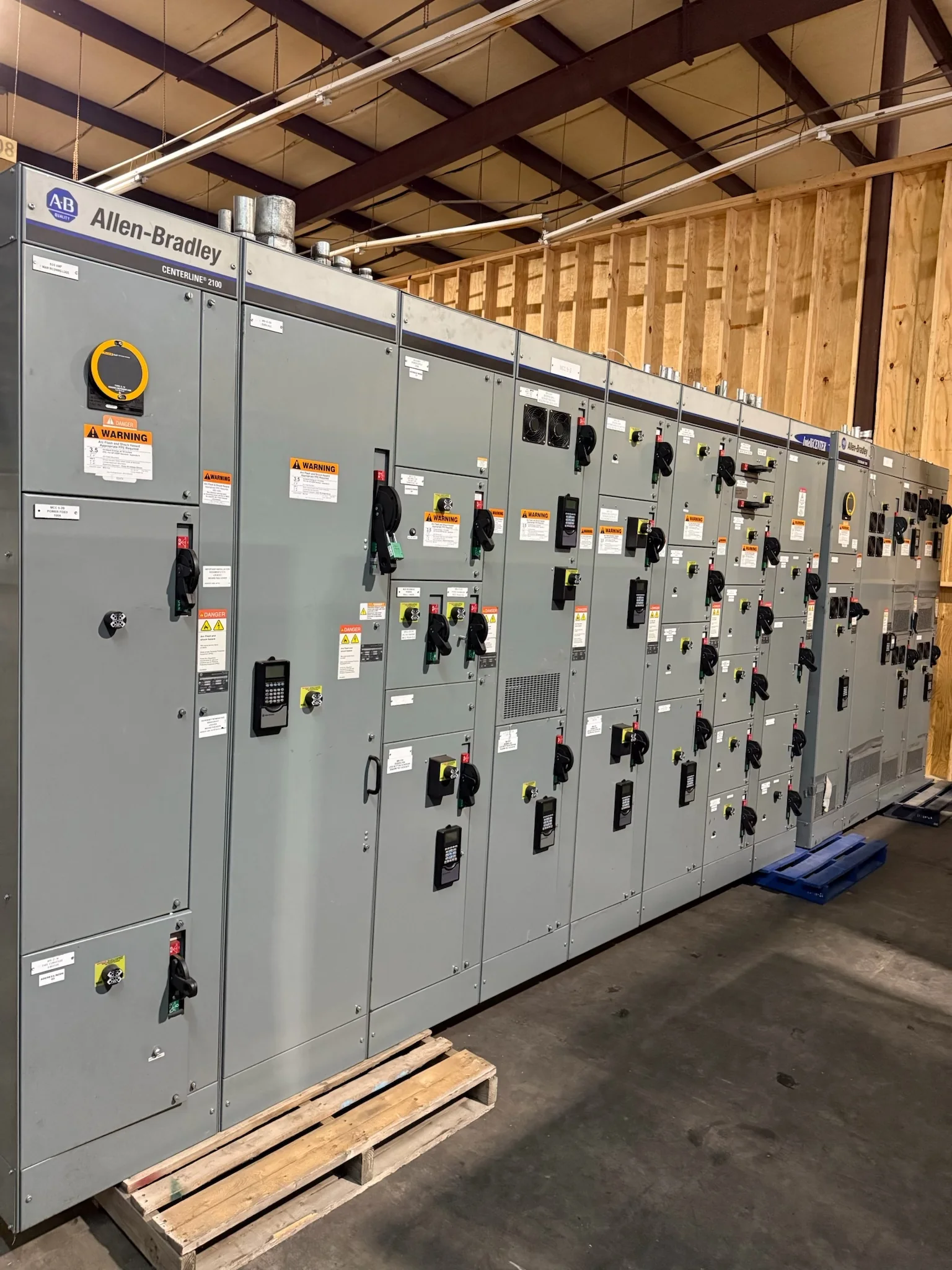
Define the Switchboard’s Role in the Distribution System
A main distribution switchboard receives power from a service, transformer, or upstream assembly and divides it among downstream feeders. Start the specification by documenting the source, system voltage, phase and wire arrangement, available fault current, grounding method, and intended load groups. These details affect bus and interrupting ratings, protective-device selection, metering, and the arrangement of sections. Confirm whether the assembly serves as service equipment or is installed downstream; that distinction can change the required disconnecting means, neutral treatment, and marking. Also identify future feeders, spare capacity, and any utility or authority requirements before the layout is set. A manufacturer can then review the requested configuration against project conditions rather than assume that a familiar switchboard arrangement suits the application.
Coordinate Ratings, Protection, and Selectivity
A switchboard’s main and feeder devices must be selected for the electrical system they protect, not simply copied from an older lineup. Provide the engineer’s one-line diagram, load schedule, fault-current information, and protective-device coordination or arc-flash study criteria when available. The review should address interrupting ratings, bus bracing, sensor or trip settings, and selective coordination where the project requires it. A change in transformer size or upstream protection can alter available fault current, so verify the source assumptions before releasing equipment for manufacture. Identify special loads, including motors, generators, UPS systems, and other sources that may affect protection or backfeed considerations. Final ratings, device combinations, and compliance obligations remain project-specific and should be confirmed by the responsible electrical design professional.


Match the Lineup to the Room and Installation Path
A sound electrical design can still create a difficult installation if the switchboard cannot reach its final position or fit its room. Compare the proposed section arrangement and dimensions with the equipment-room plan, door and corridor clearances, turning points, floor openings, and available lifting equipment. Confirm working-space requirements and access to operating handles, cable terminations, and serviceable components with the project team; applicable clearances depend on the installation and governing requirements. Specify cable entry direction, conduit locations, trench or housekeeping-pad details, and any wall or structural constraints early. These checks help avoid field changes that can delay terminations or compromise access. Because the finished configuration depends on the approved design, resolve room and access questions before the manufacturer finalizes drawings.
Specify Construction, Components, and Future Capacity
Purchasing documents should describe the intended operating environment and usable configuration, not rely on a model name alone. Identify indoor or outdoor placement, ambient and environmental conditions, enclosure preferences, bus material if specified, control power, metering, communications, and required accessories. State the number and type of feeder provisions and distinguish equipped circuits from spaces reserved for future work. A future space is not automatically a complete, ready-to-energize feeder; its bus connection, protective device, and installation requirements need explicit definition. The manufacturer offers custom builds and American components, but component selection, enclosure details, and availability must be confirmed for the particular project. For a low-voltage switchboard assembly, address whether UL 891 evaluation is required and confirm the applicable scope rather than assume the standard covers every configuration.
Prepare Drawings and Submittals for Review
A complete submittal package gives engineering, procurement, and field teams a chance to resolve mismatches before equipment is built. Send the latest one-line diagram, specifications, panel or feeder schedules, site layout, utility criteria, and applicable study assumptions together, with revision dates clearly identified. Review the manufacturer’s arrangement and connection drawings for section sequence, dimensions, cable spaces, device ratings, labeling, and incoming and outgoing conductor access. Check that metering, control interfaces, and communication points align with the project’s monitoring requirements. Mark deviations and open questions directly in the review process, then track approved revisions so installers are not working from superseded documents. Confirm the project’s required submittal format, approval milestones, and closeout records at order placement; these deliverables and their timing are project-specific.
Plan Schedule, Shipment, and Field Readiness
Discuss schedule and delivery requirements with the manufacturer while the design is being developed, since custom configuration, component availability, drawing approvals, and required documentation can affect the production sequence. Short lead times may be available, but no duration should be assumed until the specific scope and current availability are reviewed. Identify the required-on-site date, receiving hours, unloading method, staging space, delivery restrictions, and whether the shipment must be coordinated with construction phases. Nationwide shipping does not remove the need to verify access for the carrier and handling equipment at the destination. Before arrival, confirm that the room, support surface, feeder pathways, and approved drawings are ready. Installation, inspection, testing, and energization should follow the project documents and applicable requirements, with electrical work performed under appropriate safety controls.