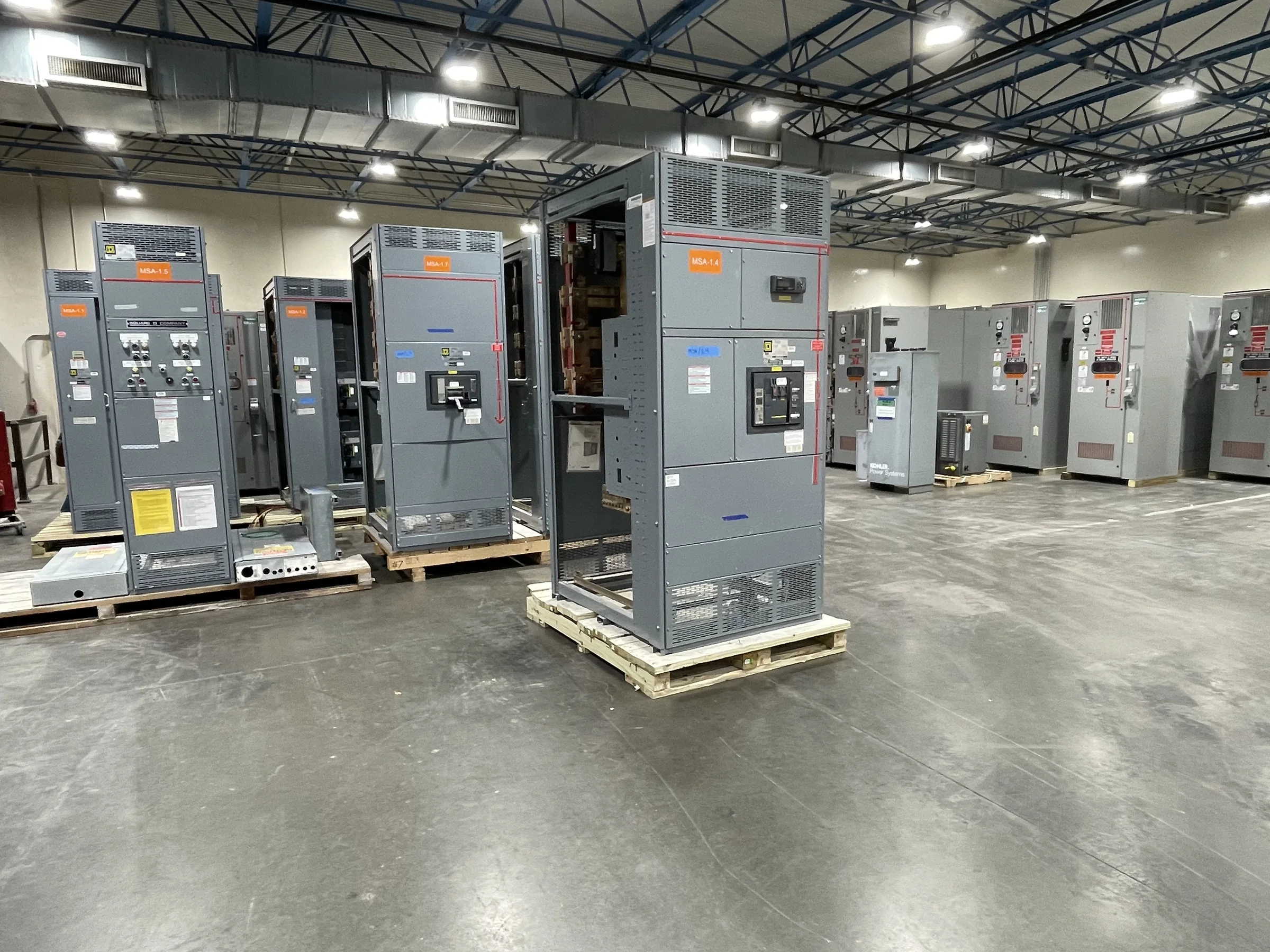
What Continuous Current Rating Means
A switchgear continuous current rating is the current an assembly can carry indefinitely under specified conditions without exceeding applicable temperature limits. It is not the same as a short-circuit rating, which addresses the equipment’s ability to withstand or interrupt fault current for a stated duty. Nor does it automatically describe the capacity of every component installed inside the lineup. Bus, circuit breakers, connectors, and terminations each have ratings and operating conditions that must be checked against the project design. For procurement, the useful question is not simply “What is the switchgear amp rating?” but whether the complete proposed configuration can carry the expected load continuously under the conditions stated in its documentation. Confirm the governing standards and evaluation basis for the specific assembly.
Match the Rating to the Load and Operating Plan
Start with the facility’s actual load profile, not only the connected-load total or the rating of an existing lineup. Identify present demand, planned additions, large motor starts, nonlinear loads, operating schedules, and any expected periods of sustained high current. A continuous rating must support the intended operating duty; a brief peak and a steady load are different design questions. Engineers should also confirm how loads are distributed among sections and feeders, because a lineup-wide figure can obscure a more heavily loaded bus segment or device. Procurement teams can use the load schedule and one-line diagram to ask bidders to identify the proposed bus and device ratings explicitly. That comparison helps expose mismatches before equipment is released for manufacture, when a change may affect both design coordination and project timing.


Check Ambient Conditions and Installation Details
The stated rating applies within defined evaluation and installation conditions, so the equipment’s surroundings matter. Review the expected ambient temperature, indoor or outdoor placement, enclosure arrangement, ventilation, elevation where relevant to the applicable design basis, and proximity to heat-producing equipment. Site conditions that differ from the assumptions behind a proposed rating can require additional engineering review; do not assume that a published or nameplate value transfers unchanged to every installation. Also check room clearances, cable-entry direction, working space, access for maintenance, and the heat load contributed by adjacent equipment. These details influence both the design and the practical installation plan. Give the manufacturer accurate site and environmental information early, and have the responsible engineer confirm any needed adjustments rather than relying on a general catalog description.
Evaluate Every Component in the Current Path
A lineup’s usable continuous-current capability depends on the complete current path and the equipment arrangement, not just the bus designation. Review the main bus, section bus, feeder devices, joints, connectors, and termination provisions against the intended load and the applicable assembly documentation. The weakest or differently rated element may limit what a section can carry in service. Device selection can also affect how current is distributed and which part of the lineup bears the duty. Ask for a clearly identified bill of materials or equipment schedule showing the ratings relevant to each position, and reconcile it with the one-line diagram. If future feeders or tie arrangements are planned, include them in the review. This prevents a nominally adequate lineup from arriving with an arrangement that does not fit the actual operating scheme.
Separate Continuous Rating from Fault Duty and Listing
Continuous current capacity does not establish that equipment is suitable for available fault current, required protection, or a particular installation. Short-circuit withstand and interrupting requirements, protective-device coordination, grounding, and system voltage are separate engineering checks. The project team should compare these requirements with the proposed equipment documentation and confirm the exact configuration being supplied. For low-voltage switchboard assemblies, UL 891 may be relevant when the assembly is appropriately evaluated to that standard; it should not be treated as a blanket certification for medium- or high-voltage equipment or assumed to apply to every product. Request the applicable drawings, ratings, and evaluation information for the specific assembly. Confirming these distinct requirements together helps avoid a purchase based on one impressive rating while another essential system or compliance need remains unresolved.
Specify, Schedule, and Coordinate Delivery Clearly
A complete request for quotation should state the system voltage, continuous-current requirements, fault-duty information, one-line diagram, load schedule, operating arrangement, enclosure and environmental conditions, cable-entry preferences, and any applicable project standards. Identify which details are fixed and which remain subject to engineering review. Accurate inputs help a U.S. manufacturer develop a custom equipment proposal and discuss component sourcing, production timing, and nationwide shipment without implying a guaranteed rating or delivery date. For planning, coordinate drawing review, approval milestones, receiving capacity, rigging access, unloading equipment, storage conditions, and the route from delivery point to electrical room. Large assemblies may require sequencing and site preparation before arrival. Confirm the shipping configuration and receiving responsibilities with the project team so that transport and installation constraints are addressed before the equipment is released.