Define the Medium-Voltage Duty Before Requesting a Quote
For a Spring facility, the first useful step is to describe what the switchgear must do in the distribution system, not just name a voltage class. Gather the service voltage, available fault-current information, grounding method, system frequency, main and feeder arrangement, and the equipment’s role in the one-line diagram. Include load characteristics such as large motors, transformers, or critical process loads, since switching and protection choices depend on the application. Identify whether the lineup will serve a utility service, plant distribution, or a dedicated process area. These details let the manufacturer assess a project-specific configuration instead of assuming a standard lineup. Confirming the design basis early can prevent mismatched interfaces, protection requirements, and costly revisions during engineering.
Coordinate Protection, Controls, and System Interfaces
Protection is not a standalone catalog choice: relay functions and settings must coordinate with upstream and downstream devices and the facility’s operating philosophy. Provide available utility data, existing protective-device information, transformer details, and the intended sequence for normal, alternate, or emergency sources. If the project includes generator paralleling, transfer schemes, remote operation, or supervisory controls, describe those interfaces before the equipment is released for design. Spring sites may have additions tied into an operating plant, where an incorrect assumption about trip signals or control power can affect more than the new lineup. A qualified project team should review coordination and settings against the actual system study. The manufacturer can use the approved requirements to develop equipment interfaces; final protection decisions remain project-specific.


Resolve Indoor, Outdoor, and Environmental Requirements
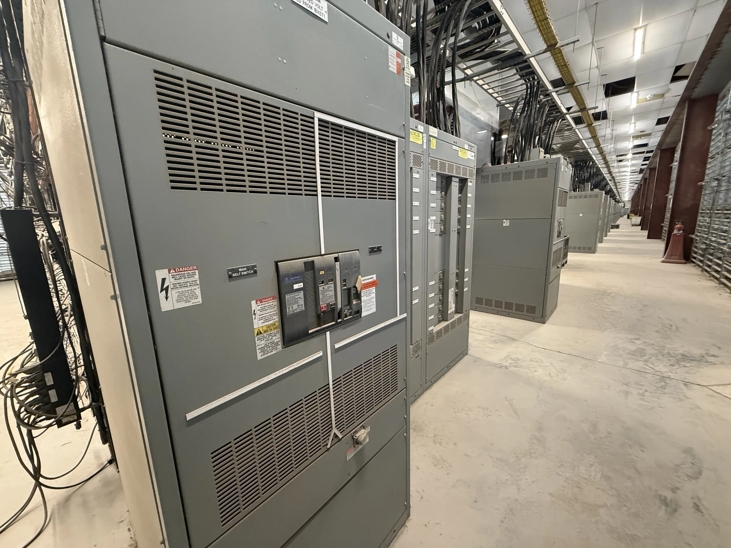
The installation environment influences enclosure selection, access, maintenance, and the equipment’s suitability for the site. Identify whether the lineup will be indoors or outdoors, the room or pad location, ambient conditions, ventilation approach, and exposure to moisture, dust, chemicals, or corrosive atmospheres. In the Spring area, heat, humidity, and seasonal storms make it especially useful to clarify building conditioning, drainage, and any outdoor exposure rather than assume a controlled electrical room. Provide room dimensions, ceiling height, door and aisle clearances, floor loading information, and the path from receiving point to final position. Those constraints can affect lineup dimensions, shipping splits, and installation planning. Confirm environmental ratings and design details against the project documents and applicable requirements.
Plan Procurement Around Approved Submittals and Site Readiness
A realistic procurement schedule starts with complete requirements and a clear review path. Identify who will approve drawings, protection and control documentation, and any required deviations; slow or conflicting reviews can delay release for manufacture. State the target in-service date, required delivery window, and any construction or shutdown milestones when requesting a quote. Short lead times may be available for some custom builds, but timing depends on the approved design, components, scope, and current production conditions; obtain project-specific confirmation rather than planning around an assumed duration. For a replacement, document the existing lineup’s dimensions, cable entry, bus arrangement, and connection points. This helps the team determine what can be reused, what needs modification, and whether adjacent equipment or outage planning must be addressed.
Document Connections, Access, and Replacement Conditions
A switchgear package is only workable when its electrical and physical interfaces fit the facility. Submit current one-line and three-line diagrams where applicable, site plans, conduit or cable schedules, control schematics, and photographs or verified measurements of existing equipment. Note top or bottom entry, conductor approach, termination space, grounding connections, and nearby obstructions. At an operating Spring facility, access through gates, occupied buildings, or restricted process areas can shape delivery and installation sequencing. Record receiving hours, crane or forklift limitations, unloading responsibility, indoor staging capacity, and any escort or site-access procedures. These details help identify conflicts before shipment and clarify which preparations belong to the owner, electrical contractor, or manufacturer. Final connection and replacement plans should be reviewed by the project’s qualified electrical professionals.
Coordinate Delivery and Compliance for the Specific Assembly
Nationwide shipping can support projects in Spring, but delivery planning still depends on the actual lineup, shipment configuration, route, receiving equipment, and site conditions. Confirm the delivery address and receiving contact during order coordination, then verify truck access, unloading arrangements, and whether the equipment can move from the drop point to the electrical room. Keep shipping splits, lifting provisions, and storage protection aligned with the approved drawings and handling instructions; unsuitable staging can expose equipment to moisture or impact before installation. For low-voltage switchboard assemblies, UL 891 may be relevant when the particular assembly is appropriately evaluated; it is not a blanket certification for medium-voltage gear. Specify required standards and documentation in the inquiry, and confirm applicability, ratings, evaluation, and availability for the exact project.