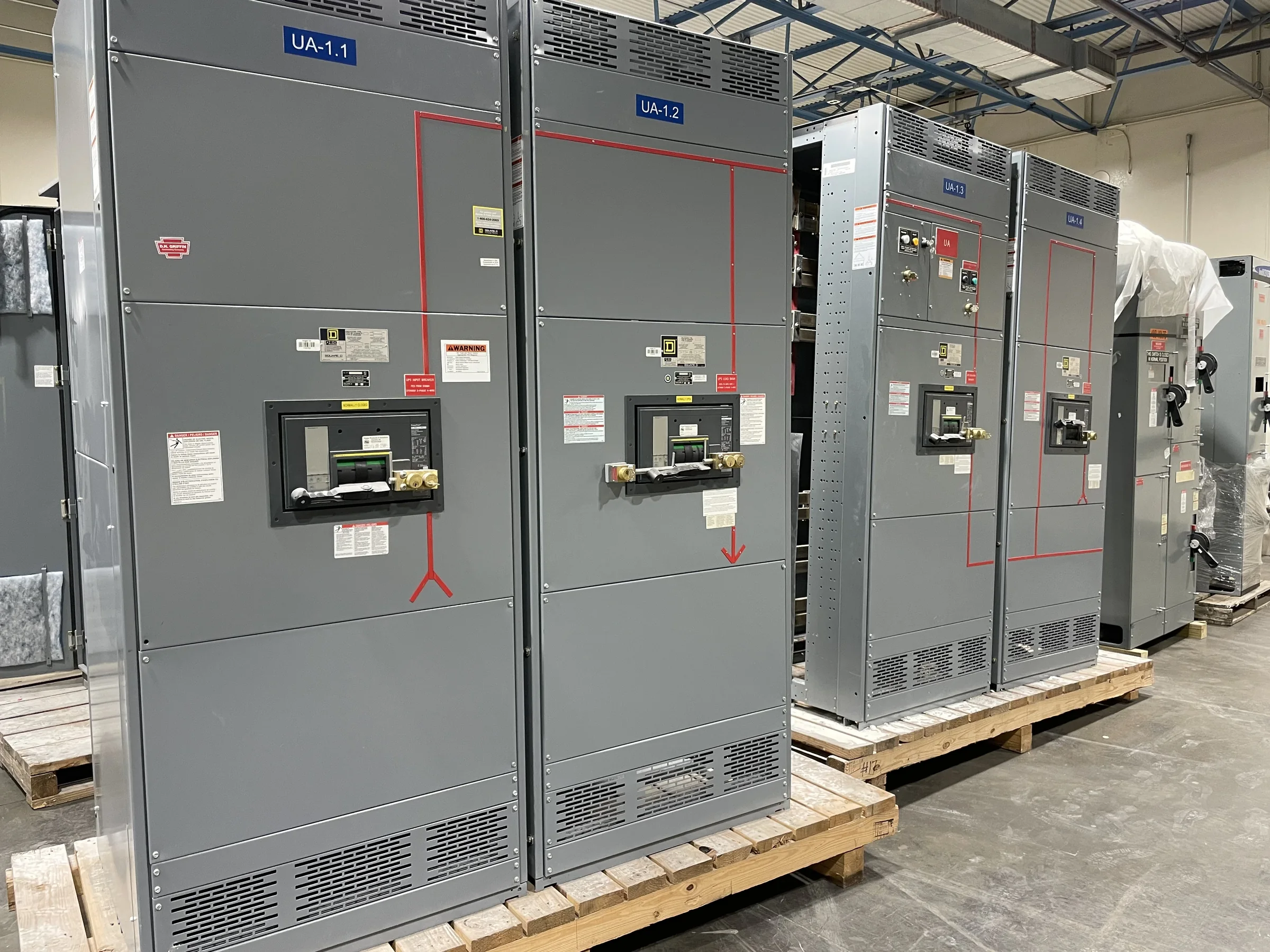
Define the Medium-Voltage Duty Before Requesting a Quote
For a Woodlands-area project, start with the electrical duty and system context rather than a preferred lineup size. Share the nominal system voltage, available fault-current information, grounding method, source configuration, and the loads or transformers the equipment will serve. Those details affect insulation coordination, interrupting requirements, bus arrangement, protective-device selection, and how the lineup connects to the existing distribution system. Identify whether the work serves a new facility, a capacity expansion, or replacement of equipment that must remain compatible with installed gear. A U.S. manufacturer can build new switchgear around project requirements, but exact ratings and configuration depend on engineering review. Early clarity reduces redesign risk and gives procurement a quote that can be compared on equivalent scope.
Coordinate Protection, Controls, and Interfaces
Medium-voltage switchgear is part of a protection and control scheme, not an isolated enclosure. Before release, align the one-line diagram with relay functions, instrument-transformer requirements, metering, control power, interlocks, communications, and upstream and downstream devices. Confirm which signals must reach a plant control system and who supplies, wires, and tests those interfaces. In The Woodlands, projects may involve utility service, campus distribution, or industrial process loads; each arrangement creates different coordination questions, so the site’s actual operating requirements should lead. A mismatch between relay settings assumptions and the available fault study can delay commissioning or leave protection decisions unresolved. Provide current studies and interface drawings when available, and clearly mark items still pending rather than treating assumptions as approved design.


Make Replacement Scope Fit the Existing Site
Replacement work often turns on details that are easy to miss in a preliminary equipment list. Record the existing lineup’s dimensions, cell arrangement, cable entry and termination space, bus connections, grounding provisions, access clearances, and relevant nameplate data. Photograph equipment and surrounding obstructions, while following site rules and keeping all inspection work de-energized and under qualified-person procedures. A new assembly may need a different footprint or transition arrangement even when its electrical function is similar. That can affect adjacent gear, cable lengths, structural supports, and the sequence for removing old equipment and setting the replacement. For a retrofit, identify what remains in service and what must be replaced; compatibility and the boundary of work require project-specific engineering, not assumptions based on voltage alone.
Build a Submittal Package That Supports Review
Procurement and engineering reviews move more smoothly when the request identifies both required deliverables and approval responsibilities. Typical project documents to define include a one-line diagram, equipment layout, elevations, schematics, bill of materials, nameplate data, and wiring or terminal information, as applicable to the scope. State the governing project specifications and applicable standards, along with required review milestones, drawing formats, and any owner or engineer comments process. UL 891 applies to appropriately evaluated low-voltage switchboard assemblies; it is not a blanket certification for medium-voltage switchgear. Do not assume a listing, test, or standard applies without confirming the equipment category and project requirements. A complete submittal basis helps expose conflicts early, especially where the new gear must interface with existing protection, control, or building systems.
Plan Timing Around Approvals and Site Readiness
A useful schedule separates engineering decisions from manufacturing and field activities instead of relying on a single delivery estimate. Identify when the fault study, relay requirements, utility data, equipment dimensions, and approved drawings will be available; late changes to these inputs can affect design completion and production sequencing. Ask the manufacturer to discuss the current project-specific schedule and the assumptions behind it, including review cycles and any customer-furnished components. For a Woodlands facility, coordinate planned outages, electrical-room access, contractor availability, and any operating restrictions with the site team well before shipment. Short lead times may be offered, but no duration should be treated as guaranteed until the design, scope, and availability are reviewed. Track open technical decisions alongside procurement milestones so unresolved interfaces do not surface at installation.
Coordinate Delivery and Installation at the Woodlands Site
Nationwide shipping does not remove the need to plan the final move into an operating facility. Confirm shipment configuration, receiving hours, unloading equipment, route limits, door and corridor clearances, floor capacity, laydown space, and protection from weather or construction activity. The Woodlands-area site may have managed access, traffic controls, or limited staging, so verify the delivery route and receiving process with facility staff and the carrier before dispatch. Determine who inspects the shipment, documents damage or shortages, and moves sections into their final position. Installation planning should also cover anchorage, bus or cable connections, grounding, control wiring, inspections, and commissioning responsibilities. Keep equipment de-energized during installation and service work; energization should follow approved procedures after qualified personnel verify the completed system.