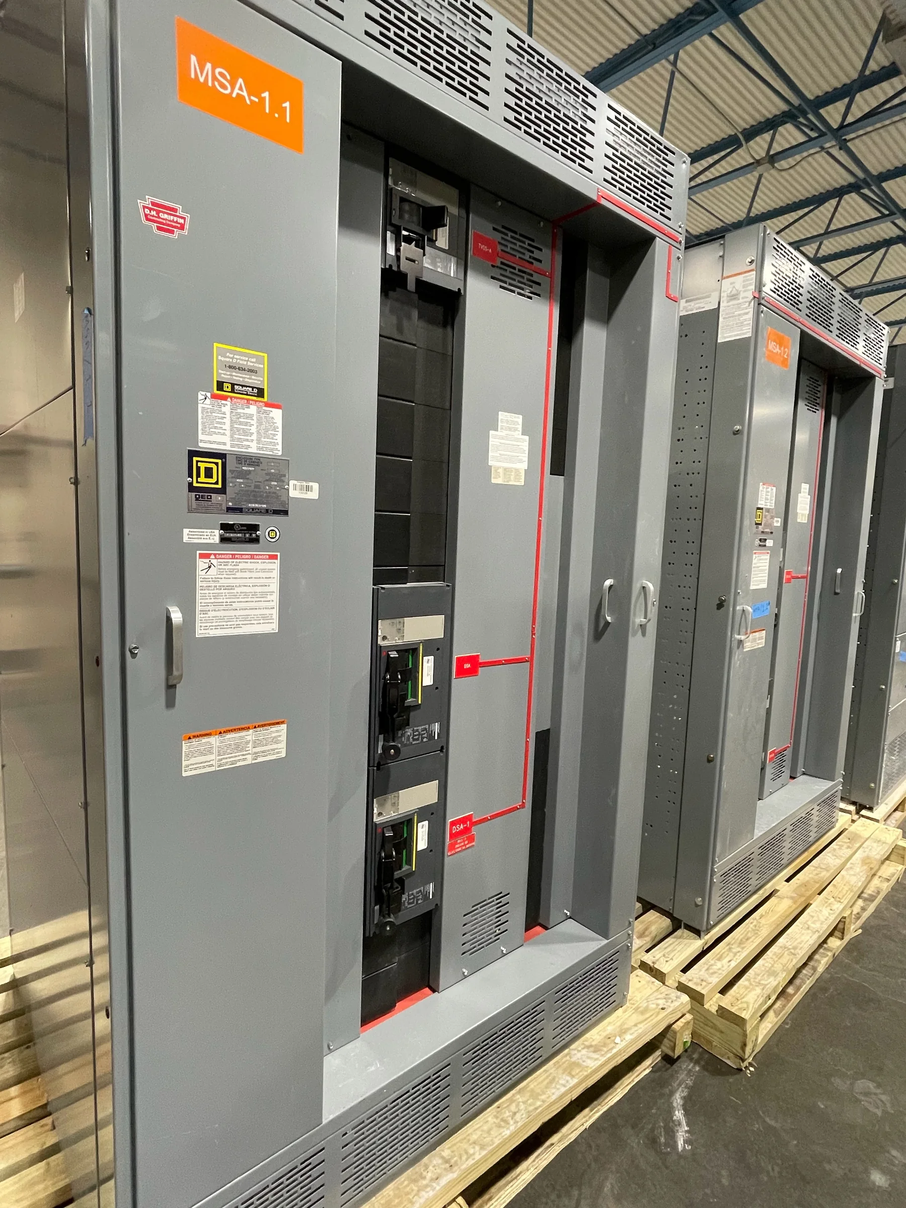
Define the System Before Selecting the Gear
Medium-voltage switchgear is selected around the electrical system it must serve, not by voltage class alone. Establish the system’s nominal and maximum voltage, frequency, available fault current, grounding method, and the required continuous current before comparing configurations. These values influence insulation coordination, interrupting and withstand duties, bus arrangements, and protective-device selection. Also identify whether the application is utility service, a plant distribution lineup, generator connection, or a dedicated process load; each can create different operating and protection requirements. Provide a current one-line diagram and note planned changes, such as added transformers or a future tie breaker. That context helps the manufacturer assess a new build against the project’s intended function. Final ratings and equipment suitability require project-specific engineering review.
Choose an Arrangement That Fits Operations
A lineup’s bus configuration and switching functions affect how the facility can isolate equipment and restore service after a fault. Decide whether the project needs a single bus, sectionalizing, a main-and-tie arrangement, or another scheme only after reviewing the operating sequence and consequences of losing each load. A tie breaker can support alternate feeds, for example, but its controls and interlocking must match the source arrangement and the site’s switching rules. Specify breaker type, metering, relaying, and any required control power as coordinated system choices rather than disconnected options. Consider access for inspection and removal of major components, too. The right arrangement can simplify maintenance or support continuity goals; it cannot compensate for an unclear protection philosophy or operating procedure.


Coordinate Protection, Controls, and Interfaces
Protection settings and switchgear functions depend on the devices upstream and downstream, so gather utility fault-current data and transformer, cable, motor, and generator information early. The engineer can use these inputs to develop a coordinated protection approach and identify required relay functions, instrument transformers, trip circuits, and control interfaces. Where the switchgear connects to an existing lineup, document the actual electrical and physical interface rather than assuming equipment from different manufacturers will align. Record control voltage, wiring conventions, communications requirements, and remote-status points when they apply. Missing interface details can delay drawing approval or create field rework, while mismatched protection assumptions may affect selective coordination. Review relay and control requirements with the responsible engineer; settings and final application are specific to the system.
Plan the Room, Access, and Installation Route
A switchgear lineup has to fit the electrical room and the path used to bring it there. Confirm available floor area, working space, ceiling height, door and corridor clearances, equipment orientation, anchoring, and cable entry locations against the proposed arrangement and applicable project requirements. Check the building’s floor capacity and identify whether walls, overhead services, or other equipment restrict movement or future component removal. Environmental conditions also matter: temperature, moisture, dust, corrosive exposure, and ventilation can affect equipment selection and room planning. Resolve these constraints before releasing fabrication drawings, because late changes may force layout revisions or installation workarounds. For replacement projects, document existing dimensions and access limitations carefully; a nominally similar lineup is not necessarily a direct physical fit.
Prepare Submittals and Resolve Scope Early
A complete request for quotation gives the manufacturer a better basis for proposing a new lineup and identifying open technical questions. Include the one-line diagram, equipment schedule, system ratings, protection requirements, preferred arrangement, control schematics if available, room layout, cable details, and applicable project specifications. Identify what the manufacturer is expected to provide and what remains with the project team, including relays, metering, communications, field wiring, installation, and commissioning. For low-voltage switchboard assemblies within its scope, UL 891 may be relevant when specified and appropriately evaluated; it is not a blanket certification for medium-voltage switchgear. Ask which standards and evaluation requirements apply to the specific equipment. Resolve deviations, drawing-review responsibilities, and approval milestones before production so procurement and engineering teams share the same scope.
Align Production Timing With Delivery Readiness
Discuss schedule and shipping requirements with the U.S. manufacturer while the design is being developed. Actual timing depends on the approved configuration, engineering reviews, component availability, and project decisions, so do not treat a preliminary estimate as a guaranteed delivery date. Set target dates for submittal review, approvals, manufacturing, inspection, shipment, and site readiness, then identify who will resolve questions at each step. Nationwide shipping still requires practical coordination: confirm the receiving address, truck access, unloading equipment, delivery hours, storage conditions, and who will inspect the shipment on arrival. If the electrical room or foundation will not be ready, plan protected storage and avoid exposing equipment to unsuitable conditions. Early coordination helps connect procurement milestones with construction needs without assuming availability before project details are confirmed.