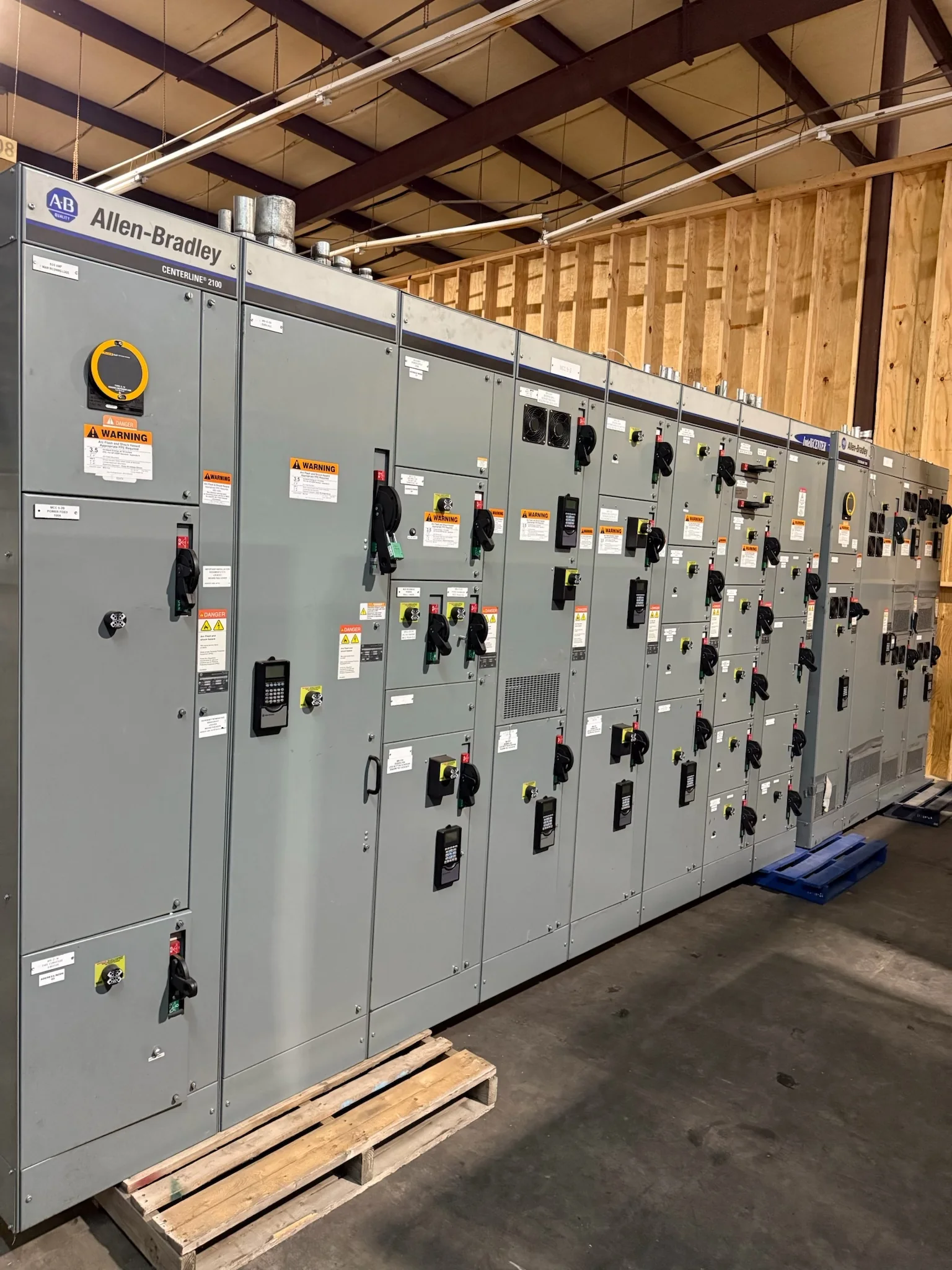
Define the Metal-Clad Lineup Around the System
Start with the electrical system the lineup must serve, not a catalog frame. Document nominal voltage, frequency, available fault current, grounding method, bus arrangement, source configuration, and required continuous-current ratings. These inputs influence the switchgear design and the coordination work that follows; a rating should not be assumed from an existing lineup’s appearance. Identify whether the project calls for incoming, tie, feeder, metering, or other functional sections, and describe normal and alternate operating conditions. Protection and control requirements also matter: relay functions, instrument-transformer needs, communications, and interlocks should be defined early enough for engineering review. Metal-clad construction separates major components into grounded compartments, but compartment layout and equipment selection remain project-specific. A complete application review helps prevent late changes that affect interfaces, drawings, and procurement.
Check Interfaces Before Selecting Replacement Equipment
Replacing existing switchgear is an interface project as much as an equipment purchase. Record the existing manufacturer and model when known, but verify field dimensions, bus connections, cable entry, conduit locations, phasing, and control wiring rather than relying on old drawings alone. Differences in compartment arrangement, breaker technology, or terminal location can turn a nominally similar replacement into a site modification. Confirm how the lineup connects to transformers, generators, protective relays, and upstream or downstream equipment, including any required transition sections. For retrofit work, define what will be replaced and what must remain; compatibility cannot be inferred from voltage class or a matching nameplate value. Share photographs, one-lines, available equipment drawings, and field measurements for review. These records help identify conflicts while the design can still be adjusted.


Coordinate Protection, Controls, and Operating Requirements
Protection settings and control functions should be considered alongside the metal-clad equipment, because a mechanically compatible lineup may still fail to meet the system’s operating needs. Provide the latest one-line diagram, a short-circuit and coordination study when available, relay requirements, and intended trip and close logic. Identify transfer schemes, permissives, remote indications, alarms, and communication protocols that must interface with plant controls. The responsible engineering team should determine whether existing studies remain valid after a change in sources, transformers, conductors, or protective devices. Specify the required instrument transformers and relay functions through the project documents, then review their application against the actual system. Clearly assign responsibility for settings, testing, and commissioning documentation. This coordination reduces uncertainty about who supplies each function and helps avoid discovering control or protection gaps during startup.
Plan the Site Work and Outage Window
A switchgear order should account for how the equipment will reach its final location and how the facility will manage the transition. Check doorway and corridor clearances, floor loading, turning space, lifting access, indoor environmental conditions, and the path from receiving to the electrical room. Confirm whether the lineup ships assembled or in sections only after the configuration and transport plan are reviewed; handling and joining requirements depend on the approved design. For replacement projects, identify outage limits, temporary power needs, demolition boundaries, and the sequence for disconnecting and reconnecting conductors. Electrical installation, inspection, testing, and commissioning require qualified personnel and a safe work plan; equipment must be de-energized before applicable work. Early site planning exposes access or shutdown constraints that could otherwise disrupt facility operations.
Build a Procurement Package That Supports Review
A clear request for quotation gives the manufacturer a basis for evaluating the application and identifying open decisions. Include the one-line diagram, equipment schedule, specification, site voltage and fault-duty information, preferred arrangement, cable entry requirements, control diagrams, and any project-specific standards. Note which requirements are mandatory and which are preferences, and flag deviations that require formal approval. Ask the supplier to identify the proposed scope, exclusions, required customer-furnished information, and submittal documents so responsibilities are visible before order placement. For applicable low-voltage switchboard assemblies, UL 891 may be relevant when the assembly is evaluated for that standard; it is not a blanket certification for metal-clad medium-voltage equipment. Confirm the applicable evaluation, ratings, and labeling for the specific design. This level of documentation supports a more useful technical and commercial review.
Review Schedule, Shipping, and Delivery Readiness
Timing depends on the final design, component selection, approved submittals, and project requirements, so discuss the schedule directly rather than planning around an assumed standard lead time. Resolve drawing comments, interface questions, and customer approvals promptly; changes after design release can affect production planning and delivery. Ask how the proposed shipment will be packaged and divided, what receiving equipment the site needs, and whether delivery must meet appointment, dock, or access restrictions. Nationwide shipping does not remove the need to coordinate unloading, indoor storage, environmental protection, and inspection on arrival. Compare the delivery plan with the outage and installation sequence, allowing time for site preparation and required field checks. A U.S. manufacturer can review a custom-build request and discuss timing, but schedule and availability remain specific to the approved project scope.