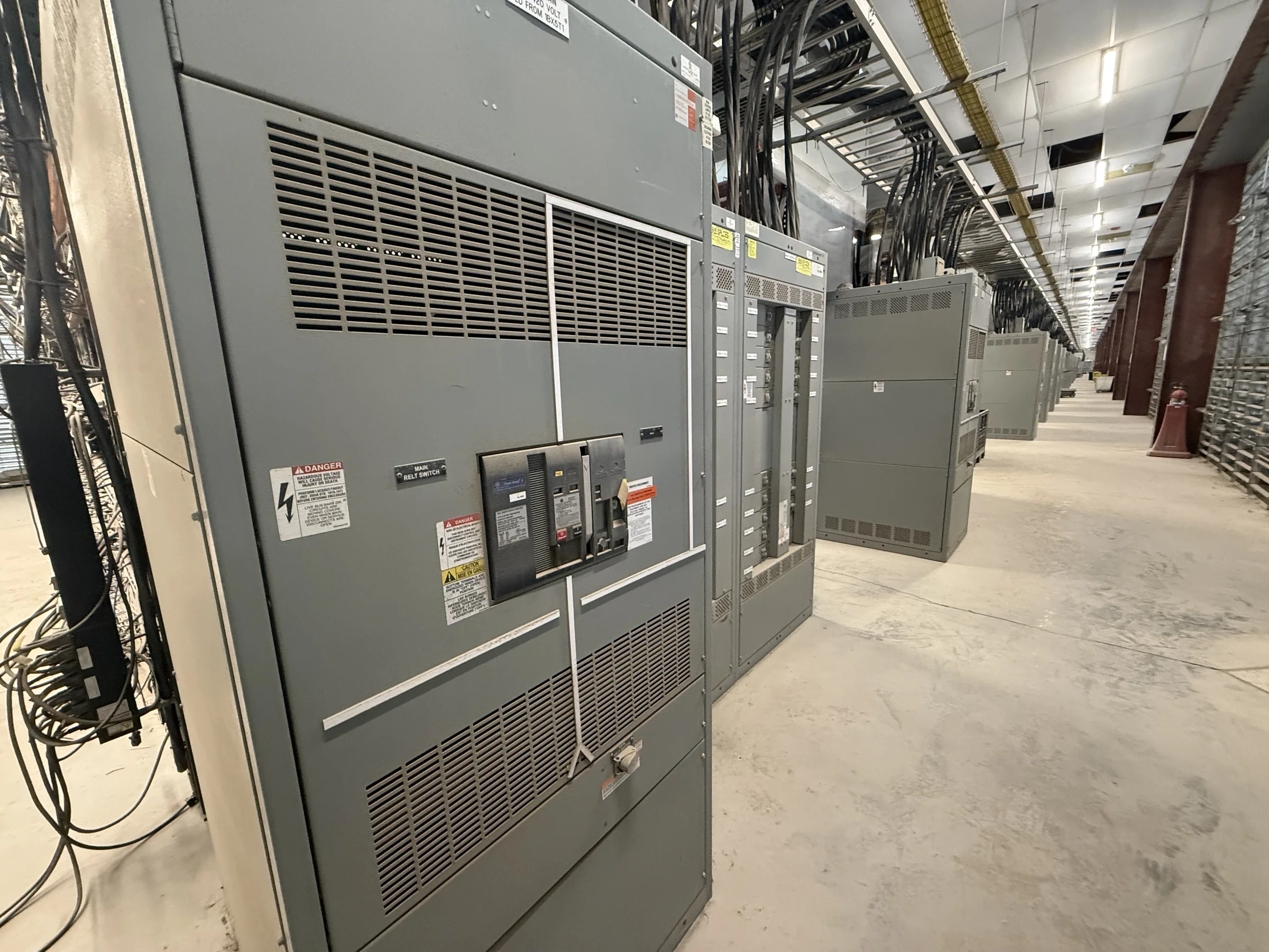
Define the System Before Selecting the Gear
Metal-enclosed switchgear is an assembly of metal-enclosed switching and interrupting equipment, but the right configuration depends on the electrical system it must serve. Start with the one-line diagram, nominal system voltage, available fault current, grounding method, load profile, and required switching functions. Identify whether the equipment is intended for service entrance, distribution, tie, or feeder duty; those roles affect the arrangement and coordination requirements. Confirm whether the project calls for medium-voltage equipment and distinguish it from low-voltage switchboards, which are governed by different construction and evaluation criteria. A U.S. manufacturer can build around project requirements, but ratings, construction, standards, and any applicable evaluation must be confirmed for the specific assembly. Resolve these fundamentals before requesting a firm technical and commercial proposal.
Coordinate Ratings, Protection, and Interfaces
A nominal voltage alone does not establish whether an assembly is suitable. The engineer and supplier need to reconcile continuous-current requirements, short-circuit withstand or interrupting duties, insulation levels where applicable, and the protective-device scheme with the system study and governing project documents. Specify breaker or switch functions, relay requirements, control power, metering, instrument transformers, and interfaces to upstream and downstream equipment. A change in transformer size, utility contribution, grounding, or operating configuration can alter fault duty and protection coordination, so assumptions should be stated rather than left implicit. Request review of the one-line diagram, control schematics, equipment schedule, and relevant studies before approving submittals. Final compatibility depends on the complete system and the selected equipment; do not treat a catalog description as confirmation of fit.


Choose an Arrangement That Supports Safe Operation
Compartment layout, access, barriers, and operating clearances affect both maintenance planning and day-to-day use. Tell the manufacturer which side or sides must be accessible, where cables enter and exit, and whether the lineup sits against a wall or in a freestanding electrical room. Note aisle dimensions, door swings, ceiling obstructions, ventilation, environmental conditions, and the route for removing major components. These details can constrain lineup width, section order, and connection design before fabrication. Establish the operating and maintenance procedures with qualified electrical personnel, including required de-energization, isolation, verification, and grounding practices; an equipment arrangement does not make energized work optional. Specify labels, mimic diagrams, interlocks, and control interfaces needed by operators, while confirming that proposed features suit the project and applicable requirements.
Make the Site and Cable Plan Buildable
A lineup that fits the electrical one-line can still fail a site review if its cable space, access, or delivery path is overlooked. Provide cable sizes and quantities, termination preferences, bend-radius constraints, conduit or busway entry points, and the location of trenches, pull boxes, and overhead obstructions. Confirm floor loading and anchorage requirements with the project’s structural team, and check the equipment footprint against room dimensions and working-space needs. For replacement work, document existing connection locations, available shutdown windows, demolition limits, and any temporary-power strategy; field verification is especially valuable where legacy drawings may not reflect current conditions. Share receiving-door dimensions, lift capacity, rigging restrictions, and staging space early. Actual shipping sections and handling needs depend on the approved design and route.
Request a Quote With Reviewable Project Inputs
A useful request for quotation lets the supplier identify gaps before they become drawing revisions or schedule disputes. Include the one-line diagram, equipment specification, load and fault-duty information, device and relay schedules, control voltage, metering scope, cable details, and required accessories. State the applicable codes or standards, project jurisdiction, submittal format, inspection or testing requirements, and any owner-specific documentation. Mark which requirements are mandatory and which are preferred, and identify deviations that need formal approval. Ask the manufacturer to clarify exclusions, customer-supplied items, interface responsibilities, and assumptions behind the proposed configuration. Compare quotations on scope and technical alignment, not just price: an omitted control feature or mismatched connection can affect commissioning and total project cost. Ratings, evaluation, and final acceptance remain project-specific.
Plan Submittals, Production, and Delivery Together
Discuss timing when the specification is still being coordinated, not after the installation date has been fixed. Drawing review, approval cycles, component selection, custom configuration, and changes to the one-line can influence production sequencing; a short lead-time offering is not a guaranteed delivery date for every design. Ask for a project-specific schedule, identify decision and approval deadlines, and track open technical questions with named owners. Before release, reconcile approved drawings with the purchase scope and verify shipping dimensions, section weights, receiving arrangements, and site readiness. Nationwide shipping can support projects across the United States, but delivery coordination still depends on the route, carrier access, unloading plan, and agreed delivery terms. Reserve time for installation, inspection, testing, and commissioning under the project plan, with all work performed using appropriate de-energized procedures.