Define the Deer Park MCC Duty Before Requesting a Quote
A motor control center (MCC) should be specified from the loads and operating conditions it will serve, not just a requested lineup length. For a Deer Park facility, identify each motor’s horsepower, voltage, full-load current, starting method, duty cycle, and control requirements, along with spare-unit expectations. Note whether loads include pumps, fans, compressors, conveyors, or process equipment, since their starting and coordination needs can differ. Provide available fault-current information and the upstream protective-device details so the design team can evaluate equipment ratings and coordination. If the data is incomplete, flag assumptions rather than treating them as confirmed. A clear load schedule helps the manufacturer develop a buildable proposal and reduces late changes that can affect footprint, components, and project timing.
Choose the Lineup for the Room and the Maintenance Plan
The MCC arrangement must fit the electrical room as well as the one-line diagram. Confirm wall clearances, working space, access routes, door swing, floor condition, and the path from the receiving point to the final location. In Deer Park, an installation may also need coordination around operating process areas, restricted access, or limited laydown space; verify those constraints with the site team rather than assuming a delivery truck can reach the gear directly. Discuss top or bottom cable entry, conduit locations, and whether rear access is practical. These choices affect enclosure layout and installation labor. Consider how technicians will isolate and service units, and how future feeders or buckets may be accommodated. A room plan and access review can prevent costly field modifications.


Match Motor Starters and Controls to the Process
Starter selection should follow the motor and process requirements. Across-the-line, reduced-voltage, and variable-frequency applications have different effects on starting current, acceleration, heat, and control integration; the appropriate choice depends on the load, power system, and operating sequence. Identify required overload protection, control voltage, interlocks, local controls, and interfaces to plant control systems. For drives, provide motor and application data and clarify whether bypass, input protection, filtering, or communications are required. Do not assume that existing control wiring or network protocols will transfer unchanged to a replacement lineup. Documenting these details early helps engineers assess compatibility and avoids discovering during commissioning that a starter behaves differently from the process sequence. Final selections and ratings remain subject to project review.
Coordinate Fault Ratings, Protection, and Existing Gear
Replacement work in an operating facility calls for a careful review of the existing electrical system. Gather current one-line diagrams, transformer data, protective-device settings, available fault-current calculations, and the nameplate information for connected equipment. Older drawings may not reflect later utility, transformer, or distribution changes, so have qualified personnel verify field conditions and resolve discrepancies before the new MCC is finalized. Confirm feeder voltage, phase, grounding arrangement, bus requirements, and the intended protective-device coordination. These details influence equipment suitability and how the lineup interfaces with upstream and downstream gear. Never infer that a new assembly will match an existing section based on appearance or nominal voltage alone. Engineering review can identify interface risks before procurement and help plan a controlled, de-energized installation.
Plan Submittals, Procurement, and Delivery Around Site Readiness
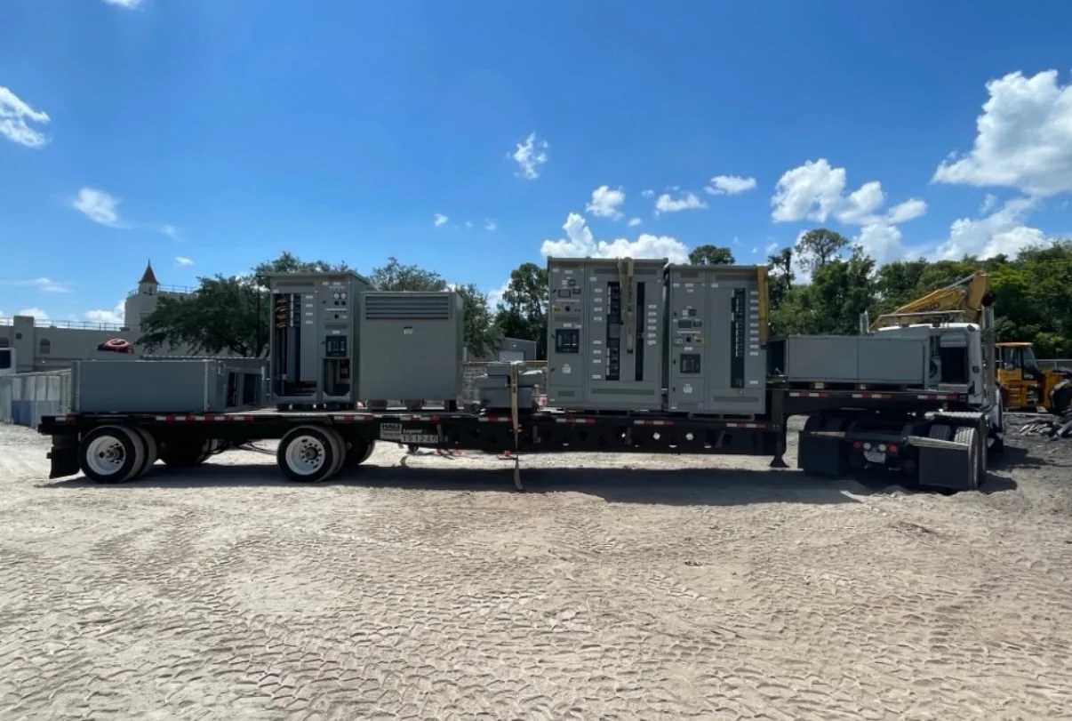
A realistic procurement schedule starts with complete requirements and a clear approval path. Share the required in-service date, drawing-review milestones, owner standards, approved component preferences, and any outage or construction-window constraints when requesting a quote. Custom builds and component availability can influence timing, so confirm project-specific status with the manufacturer rather than relying on a general lead-time assumption. Review shop drawings for dimensions, unit arrangement, cable entry, control interfaces, and nameplate details before release to production. For delivery to Deer Park, coordinate receiving hours, truck access, unloading equipment, escort rules, and temporary storage with the site. Nationwide shipping does not remove the need for local planning: missed access or an unprepared room can delay setting the equipment even after it arrives.
Document Acceptance, Installation, and Future Maintenance
A useful turnover package connects the approved design to safe operation and long-term service. Specify the drawings, bills of material, wiring diagrams, unit schedules, labels, and operation or maintenance information required by the owner. Confirm inspection and acceptance requirements with the project team, including any applicable evaluation or labeling expectations. UL 891 applies to appropriately evaluated low-voltage switchboard assemblies; it is not a blanket certification for MCCs or medium- and high-voltage equipment. Verify the standards and exact product scope for the proposed assembly rather than assuming a listing applies. Before installation, qualified personnel should confirm site conditions and follow the facility’s safety procedures, with electrical work performed de-energized. Accurate records of settings, spare units, and control interfaces make later troubleshooting and planned expansion more manageable.