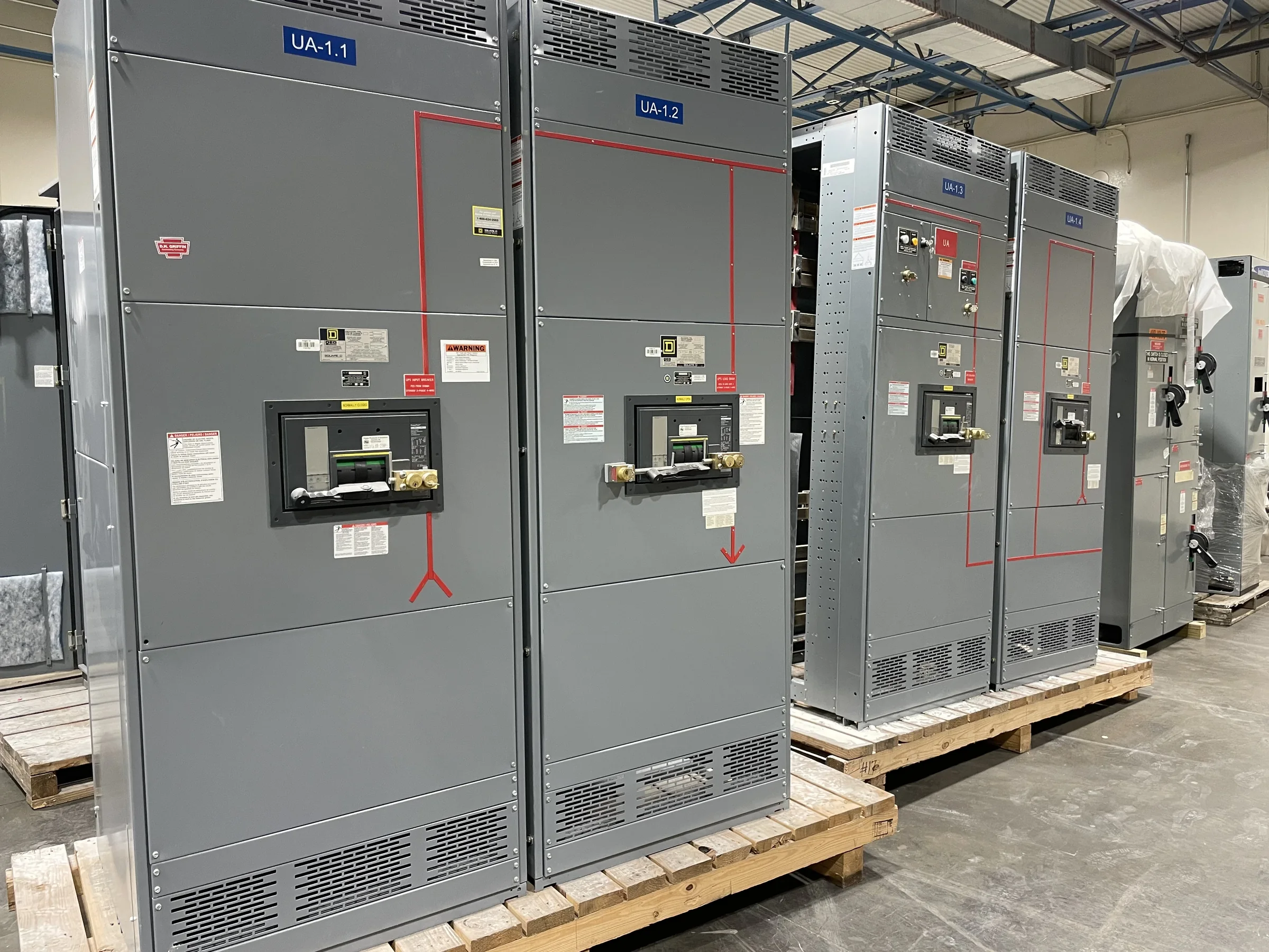
Define the MCC Around the Motor Loads
A motor control center (MCC) should be specified from the loads and operating requirements it will serve, not from a lineup label alone. For a Pearland project, start with a complete motor schedule: horsepower, voltage, full-load current, starting method, duty cycle, and the equipment each motor drives. Identify which motors need across-the-line starters, reduced-voltage starting, or variable-frequency drives, and note any required control voltage or communications. These choices affect unit construction, heat dissipation, bus loading, and the space reserved for future additions. Also distinguish continuous process loads from intermittent or standby equipment; treating them alike can produce an unsuitable arrangement. Final ratings, protective-device selections, and compatibility with the facility’s available fault current must be confirmed for the specific installation.
Resolve System Interfaces Before Requesting a Quote
An MCC does not operate in isolation: its incoming supply, upstream protection, grounding arrangement, and control interfaces all shape the build. Provide one-line diagrams and available system data, including voltage, phase, frequency, source configuration, and calculated or documented available fault current at the equipment location. Identify whether the lineup connects to a transformer, switchboard, generator, or other source, and explain any transfer or interlocking requirements. For each controlled machine, clarify who supplies field wiring, sensors, permissives, and network connections. These details matter because an assumed interface can leave gaps between the MCC and the process control system. A manufacturer can review the supplied project requirements and discuss a custom configuration; final design, protective coordination, and code compliance remain specific to the project and subject to appropriate engineering review.


Coordinate Construction Timing With Approval Milestones
When an MCC is tied to a plant expansion or equipment replacement, the schedule depends on more than fabrication duration. Establish when approved drawings, final motor data, control narratives, and release authorization will be available, then align those milestones with the site’s outage plan and contractor sequence. Late revisions to bucket sizes, drive selections, or network interfaces can affect drawings and procurement, so identify open decisions early and assign an owner for each. Discuss current component availability and anticipated manufacturing timing directly with the U.S. manufacturer; short lead times may be offered, but a project-specific schedule should not be treated as guaranteed until scope and dependencies are reviewed. Build time into the plan for submittal review, shipment coordination, receiving, installation, inspection, and commissioning rather than counting only the equipment build.
Plan the Pearland Delivery Route and Receiving
A delivery that reaches the Pearland site still has to reach the electrical room safely and on schedule. Before release, confirm truck access, gate and security procedures, unloading equipment, receiving hours, and the path from the drop point to the installation area. Check doorway and corridor clearances, turning space, floor loading, and any restrictions on moving lineup sections through the building. Construction activity, changing access controls, and coordination with other trades can make a previously suitable route unavailable. Arrange who will inspect the shipment, document visible damage, and stage the equipment in a clean, dry, protected area. Nationwide shipping can support a Texas project, but routing, unloading responsibility, shipment configuration, and delivery dates should be coordinated for the actual site rather than assumed from the destination city.
Prepare the Room and Installation Package
Room readiness can determine whether an MCC is installed efficiently or held at the threshold. Compare the proposed lineup arrangement with current architectural and electrical drawings, confirming working space, egress, door swing, cable-entry access, and the planned route for conductors. Verify housekeeping-pad or floor details, anchorage expectations, environmental conditions, and ventilation needs against the equipment documents and applicable project requirements. Where existing gear is being replaced, record field dimensions and cable locations before finalizing the configuration; legacy arrangements may not match current drawings. The submittal package should identify the lineup sections, ratings, unit schedule, connection points, and required interfaces clearly enough for engineering and installation review. Exact construction, standards, and any applicable evaluation or labeling must be established for the selected assembly, not presumed from a product category.
Make Startup and Future Service Part of the Specification
Procurement decisions should account for the people who will operate and maintain the MCC after turnover. Specify operator access, device identification, control documentation, spare-unit strategy, and any desired provision for future loads, while recognizing that extra space or capacity must be verified against the final design. Request drawings, nameplate information, device schedules, and operation or maintenance materials appropriate to the purchased configuration. Before energization, qualified personnel should verify installation, grounding, connections, protection settings, and control interfaces using approved project procedures; testing and startup scope should be assigned clearly among the manufacturer, contractor, and commissioning team. De-energized work and applicable safety procedures are essential. A Pearland facility’s maintenance and production teams should review the plan together so shutdown windows, access, and handoff records are practical for the equipment’s intended use.