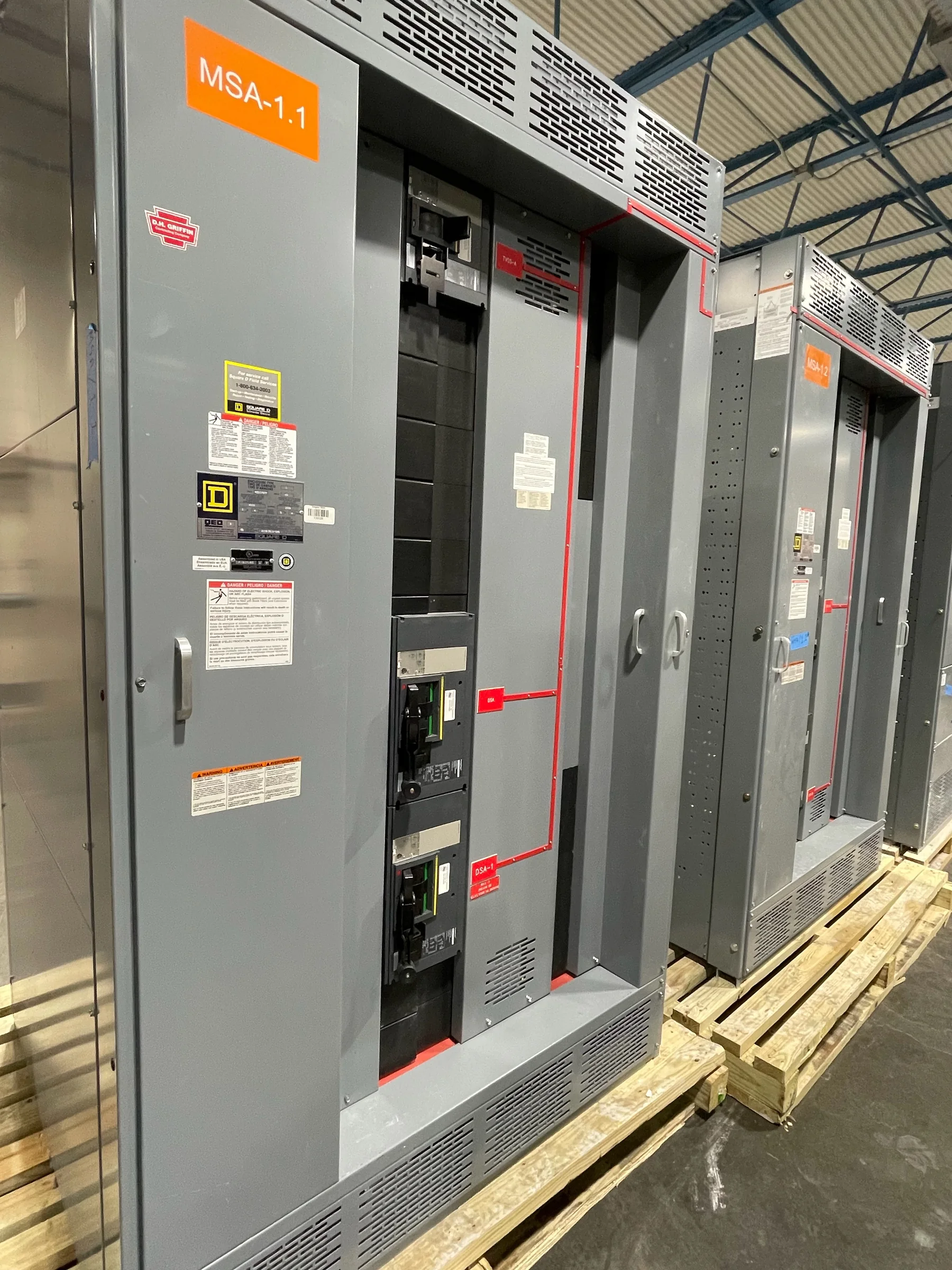
Define the Motor Control Center Around the Loads
Start the specification with the equipment each motor control center (MCC) will serve, rather than a preferred lineup size. Provide motor horsepower, voltage, full-load current, starting method, duty, and whether loads operate continuously, intermittently, or in a sequence. Identify the driven equipment and any required control interfaces, such as PLC signals, permissives, alarms, or local operator stations. These details affect starter selection, feeder organization, control wiring, and the space reserved for future units. For a Woodlands-area facility, include the actual process and building conditions; an office, water system, and industrial process may have very different operating demands. The manufacturer can use the project’s load schedule and one-line diagram to develop a proposed arrangement, with ratings and compatibility confirmed for the application.
Choose Starters and Controls for Operating Conditions
Across the lineup, starter type should follow the motor’s operating requirements and the facility’s control strategy. Full-voltage starters, reduced-voltage methods, and variable-frequency drives have different implications for starting current, acceleration, process control, heat, and maintenance. A drive may support adjustable speed, but its suitability depends on the motor, driven load, control scheme, and electrical system; it should not be selected solely as a presumed energy-saving upgrade. Document which motors need speed control, reversing, jogging, coordinated starts, or local operation. Also state who supplies drives, overload settings, sensors, and control devices, and identify any required communications protocol. Resolving these boundaries before ordering helps prevent missing components, mismatched control interfaces, and startup delays when the MCC is integrated with plant automation.


Confirm Electrical Ratings and System Coordination
The available fault current and upstream protective-device information are essential inputs to an MCC specification. Share the system voltage, source and transformer data, one-line diagram, and protective-device details so the design team can evaluate applicable short-circuit ratings and coordination requirements. Do not assume a rating from an existing lineup transfers to replacement equipment: changes to utility service, transformers, feeder length, or protective devices can change the conditions. Confirm the required bus rating, enclosure and environmental conditions, grounding arrangement, and any arc-flash or selective-coordination study requirements with the responsible engineer. Ratings, code requirements, and equipment compatibility must be verified for the specific project. This review matters because an assembly must be suitable for the installation’s electrical conditions, not merely fit its physical location.
Plan the Lineup for Woodlands-Area Site Conditions
Measure the installation route as carefully as the electrical room. Record doorway and corridor clearances, ceiling height, floor capacity, turning space, available working space, and the location of existing conduits, cable trays, and overhead services. In The Woodlands, delivery planning may also involve coordinating access through a managed campus, commercial complex, or active industrial site; verify receiving hours, truck restrictions, security procedures, unloading equipment, and temporary staging with the site team. If the equipment will be outdoors or near humid, corrosive, dusty, or washdown conditions, specify the actual exposure and required enclosure conditions for engineering review. These checks influence shipment configuration and placement planning. A lineup that meets electrical needs can still create costly installation changes if access, handling, or its environment was overlooked.
Align Schedule, Submittals, and Procurement Scope
Set timing expectations by tying the requested delivery window to defined project milestones, not by assuming a standard lead time. Identify when approved submittals, final drawings, control schematics, and interface details are needed; note any long-lead project components or decisions still pending. Ask for the proposed scope to distinguish furnished equipment from field installation, upstream protection, programming, and commissioning. The manufacturer offers custom builds, American components, short lead times, and nationwide shipping, but specific availability, delivery timing, and configuration depend on the approved requirements and current project conditions. Confirm the shipping destination, receiving contact, site access, and who unloads and moves the equipment into place. Early scope alignment helps procurement compare proposals fairly and reduces the risk of schedule gaps caused by exclusions or unresolved approvals.
Review Documentation Before Release and Installation
Before authorizing production, compare the submittal package with the project’s one-line diagram, load schedule, control narratives, and room layout. Check unit names and quantities, motor data, starter and drive requirements, control voltage and interfaces, incoming and outgoing connections, and any specified accessories. Resolve discrepancies in writing; an undocumented assumption about a spare unit, remote command, or conduit entry can complicate installation and startup. Request the drawings and manuals needed for site preparation, inspection, operation, and maintenance, and confirm that revisions reach the electrical contractor and controls team. For low-voltage switchboard assemblies, UL 891 may be relevant when the assembly is appropriately evaluated; it is not a blanket certification for every MCC or voltage class. Verify applicable standards and labeling for the specific supplied equipment.