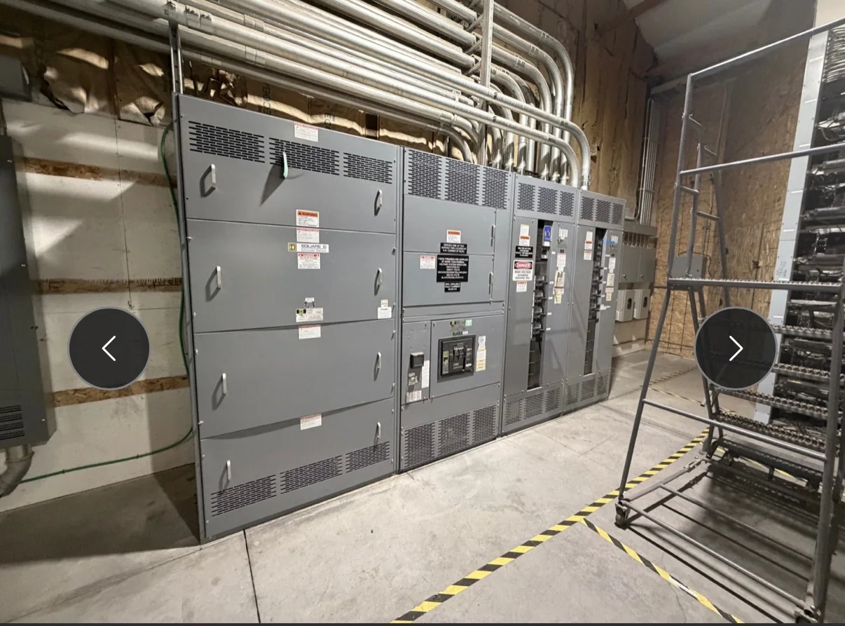
Define the MCC Around the Loads It Must Control
A motor control center (MCC) groups motor-control units and related equipment in a coordinated assembly, but the lineup should begin with the actual load list—not a standard bucket arrangement. Document each motor’s nameplate data, starting method, operating duty, control voltage, and any required disconnect, overload protection, or short-circuit protection. Include non-motor loads only when their function and the proposed arrangement are confirmed. These details affect unit selection, internal bus requirements, heat and space planning, and the controls needed for safe operation. Identify which motors are critical to production and whether local, remote, or automatic control is expected. A complete load schedule helps the manufacturer develop a project-specific configuration and gives engineering, procurement, and operations a shared basis for reviewing the proposed equipment.
Choose Starters and Drives for the Process
Across a process line, not every motor should be controlled the same way. Across-the-line starters can suit straightforward fixed-speed duties, while reduced-voltage starting or variable-frequency drives may be considered when the process, electrical system, or mechanical equipment calls for a different starting or speed-control approach. Selection depends on motor characteristics, load behavior, starting frequency, available fault current, and coordination with upstream protection; it should not be made from horsepower alone. Drives also introduce enclosure, cooling, harmonic, and maintenance considerations that can affect the lineup and surrounding room. Tell the manufacturer which functions are essential—such as speed reference, interlocks, alarms, or communications—and which are optional. The engineer can then evaluate a suitable arrangement without treating any device combination as universally compatible.


Coordinate Ratings, Fault Duty, and System Interfaces
An MCC must fit the electrical system it connects to, not simply match a preferred catalog description. Provide the system voltage, frequency, grounding method, available short-circuit current at the equipment, upstream protective-device information, and the intended connection arrangement. These inputs help determine whether proposed bus, units, and protective devices can be evaluated for the application. Confirm how the MCC interfaces with the service or distribution equipment, including incoming conductors, cable entry, and any required transition section. Available fault current and protective-device coordination are especially important: a mismatch can affect equipment suitability and the protection of connected circuits. Final ratings, construction, and applicable standards are project-specific, so review them against the actual system study and approved drawings before release rather than relying on an assumed standard configuration.
Resolve Layout, Access, and Environmental Conditions
A workable lineup needs more than enough floor area for its footprint. Confirm room dimensions, door and corridor clearances, access for installation and maintenance, overhead obstructions, cable-tray routes, and the path from receiving to the final position. Record whether conductors enter from above or below and identify nearby walls or equipment that could restrict access. Ambient temperature, dust, moisture, corrosive exposure, and ventilation can influence enclosure choices and drive cooling; the room conditions should be stated rather than left to assumption. Also check working-space requirements and applicable code provisions with the responsible electrical professional. These checks matter before fabrication because a lineup that fits on a drawing may still be impossible to move into place, connect, or service safely in the actual facility.
Submit Documents That Support a Clean Review
A focused request for quote can reduce avoidable design revisions. Include the one-line diagram, motor schedule, control narrative, equipment location and layout, system data, and any owner or consultant specifications available at the time of inquiry. Mark open decisions clearly—for example, a pending fault-current study or an undecided drive interface—so they are not mistaken for approved requirements. Ask the manufacturer to identify assumptions and exceptions in its proposal, then have engineering and operations review the unit schedule, elevations, wiring information, and interface details before approval. Document control matters: inconsistent drawing revisions can lead procurement and installation teams to work from different arrangements. Confirm who approves technical submittals, who supplies field wiring and network details, and which documents are needed for installation, operation, and maintenance.
Plan Production and Delivery Around Site Readiness
Project timing depends on the approved scope, component availability, drawing review, and the sequence of decisions—not on a generic lead-time promise. When requesting a quote, share the required in-service date and note any commissioning milestones, shutdown windows, or phased installation plans. Ask which approvals or customer-furnished information must be complete before production proceeds, and confirm how proposed changes are handled after drawing approval. For delivery, verify the receiving location, unloading equipment, access restrictions, storage conditions, and who will inspect and accept the shipment. Nationwide shipping can support projects across the United States, but site access and coordination remain the project team’s responsibility. A realistic schedule connects manufacturing milestones to site preparation, qualified installation, and testing performed under the approved project procedures.