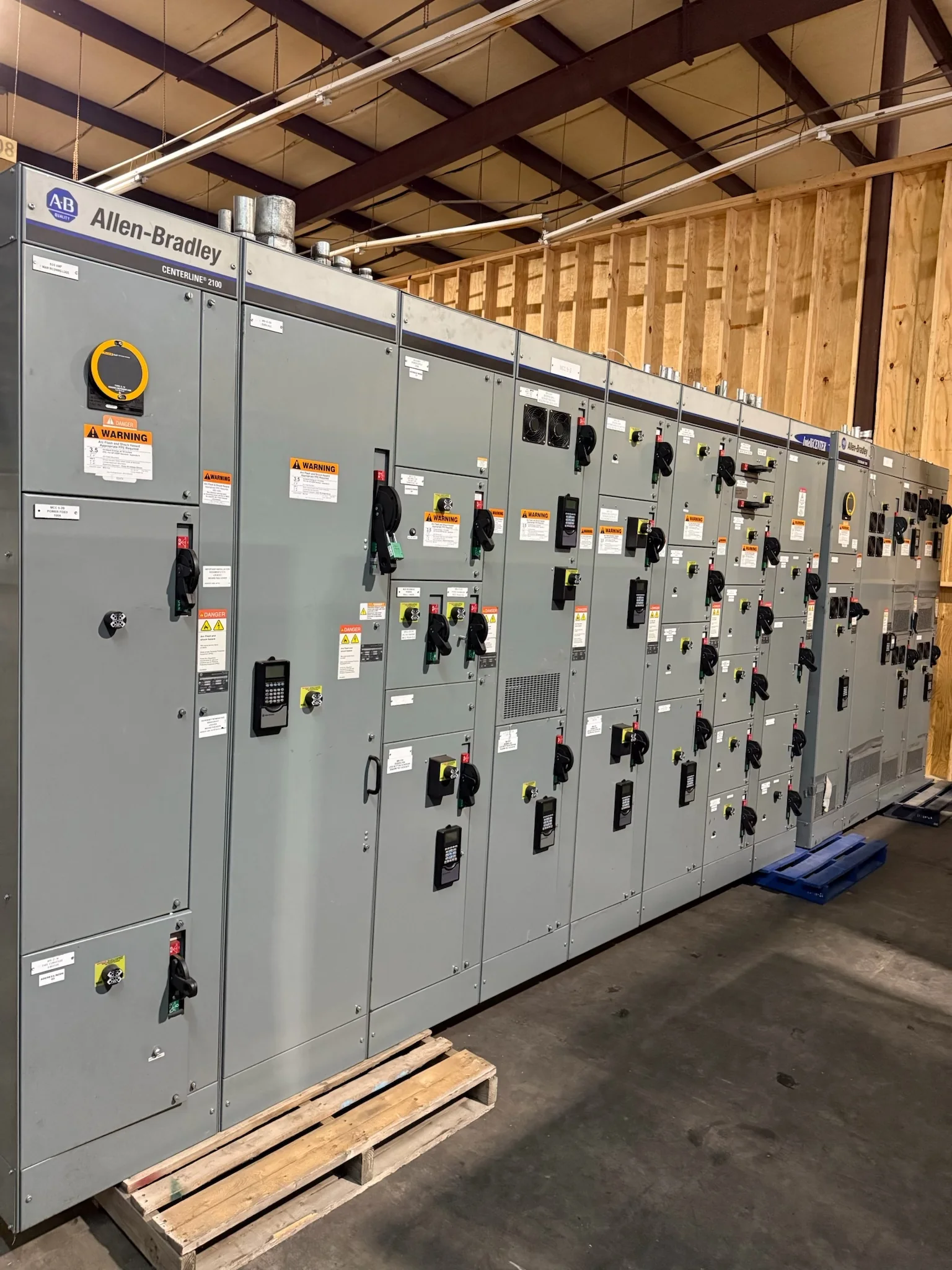
Start With the Facility’s Electrical Duty
Oil and gas sites can combine process loads, utility services, buildings, and remote equipment on one distribution plan, but their switchgear requirements are not interchangeable. Begin with the one-line diagram, system voltage, available fault current, load list, and the operating sequence the equipment must support. Identify whether the lineup serves a gathering station, processing plant, refinery area, pipeline facility, or another application; each can impose different continuity and coordination priorities. Include expected motor starting, future load additions, and the consequences of losing each bus or feeder. These details help the manufacturer develop a suitable new assembly rather than relying on a generic product description. Final ratings, construction, and applicable standards depend on the engineered design and project evaluation.
Account for Hazardous Locations and Environmental Exposure
Classified areas, corrosive atmospheres, dust, moisture, temperature extremes, and vibration can affect where switchgear may be installed and how the surrounding electrical system is arranged. Provide the project’s area-classification documents and equipment-location drawings so the engineering team can distinguish the switchgear room from nearby classified spaces. Do not assume that a standard indoor lineup is suitable for outdoor service or for direct exposure to process conditions. Specify the enclosure environment, ventilation or cooling approach, access clearances, and any site requirements for coatings or materials; confirm these against the actual design and applicable codes. This information matters because a mismatch can complicate approval, installation, or maintenance. The final equipment arrangement and environmental provisions must be confirmed for the specific site.


Coordinate Protection, Controls, and Operating Continuity
Protection decisions should reflect the facility’s source configuration, feeder arrangement, motor loads, and required response to faults—not simply the nominal size of the switchgear. Share available short-circuit data, protective-device settings where established, transformer information, and coordination or arc-flash study requirements. Clarify whether the project calls for metering, alarms, remote indications, communications, interlocking, or integration with plant control systems. Also describe normal and contingency operating modes, including how operators are expected to isolate a section for maintenance. These inputs affect device selection, instrument-transformer needs, control wiring, and documentation. A qualified project engineer must verify the protection and control design. Confirming responsibilities and interface points early helps reduce gaps between the switchgear package, upstream supply, downstream equipment, and site controls.
Resolve Layout and Installation Constraints Before Release
A technically acceptable lineup still has to fit the building, electrical room, or equipment shelter and reach its final position. Provide room plans, door and aisle dimensions, ceiling height, cable-entry direction, duct or trench locations, and the route from receiving point to foundation. Note lifting limits, rigging access, floor loading, seismic criteria if applicable, and restrictions on shipping splits or assembly at the site. These constraints matter because a late discovery can force layout changes or additional field work. Establish the intended cable terminations and verify working clearances against the project design and governing requirements. When specifying replacement equipment, document existing connections and dimensions, but do not assume a new assembly will be a direct fit without engineering review.
Make Submittals and Commercial Scope Comparable
A useful request for quotation gives suppliers the same technical and commercial basis for response. Include the latest one-line diagram, equipment schedule, load and fault data, room layout, applicable project specifications, preferred delivery destination, and required submittal format. Identify the requested scope clearly: switchgear assembly, protective devices, metering, control components, documentation, and any separately furnished or site-installed items. Ask the manufacturer to identify exceptions, information gaps, and assumptions rather than treating silence as acceptance. For low-voltage switchboard assemblies, UL 891 may be relevant when the project and assembly are appropriately evaluated; it is not a blanket certification for medium- or high-voltage equipment. Confirm the required standards, evaluation, labeling, and acceptance criteria for the actual equipment in the project documents.
Plan Timing, Shipping, and Site Receipt Together
Discuss schedule at the start of procurement, using the approved scope, drawing review, required submittals, and project milestones to establish a realistic path. Custom builds and component selection can affect timing, and a quoted schedule should be confirmed for the specific configuration and order rather than treated as universal. Coordinate nationwide shipping with the facility’s receiving hours, unloading capability, storage conditions, access controls, and delivery appointment process. Confirm shipment packaging, handling responsibilities, and who will inspect and document equipment on arrival. This matters at remote or controlled industrial sites, where a missed delivery window or unavailable lifting equipment can disrupt installation planning. The manufacturer can discuss project-specific timing and delivery arrangements; final availability, shipment details, and installation readiness must be verified for each order.