Start With the Electrical Duty and Installation Setting
Outdoor switchgear selection begins with the system it must serve, not simply the enclosure location. Define the nominal voltage, available fault current, continuous load, source arrangement, and intended switching or protective functions with the project engineer. These inputs shape the equipment configuration and help avoid specifying an assembly that cannot coordinate with upstream protection or meet the system’s duty. Also establish whether the installation serves a utility interface, industrial process, commercial facility, campus, or other application; operating practices and continuity needs differ. The manufacturer can build new equipment around project requirements, but ratings, construction, and applicable standards must be confirmed for the specific assembly. Supplying a one-line diagram and equipment schedule early gives the engineering and estimating teams a sound basis for review.
Choose an Enclosure for the Actual Exposure
An outdoor location exposes electrical equipment to conditions that indoor switchgear does not face: rain, snow, windblown dust, sunlight, temperature swings, condensation, and potentially corrosive atmospheres. Document the site’s climate and contaminants, including coastal salt, industrial chemicals, or washdown exposure where relevant. Then review enclosure construction, access doors, ventilation strategy, drainage, and finish with the equipment supplier and design team. An enclosure that limits water entry still needs to manage heat from the installed components; poor ventilation or unaccounted solar gain can affect internal temperatures and equipment life. Consider roof overhangs, nearby structures, and prevailing weather, while avoiding assumptions that a general-purpose outdoor enclosure suits every exposure. The required enclosure type and environmental suitability are project-specific and should be stated in the procurement documents.


Plan Clearances, Access, and the Foundation
The site layout must support safe operation and future maintenance, not just fit the equipment footprint on a drawing. Check working space, door swing, operating access, cable entry routes, lifting and rigging access, and the path for eventual component removal. Coordinate these needs with applicable electrical codes and the project’s safety requirements; required clearances depend on the installation. The civil team should confirm foundation dimensions, elevation, anchor locations, drainage, conduit stub-ups, and soil or structural conditions before fabrication details are finalized. Poorly placed conduits can obstruct internal cable space or force difficult field bends, while standing water near the base can accelerate deterioration. Resolve interface points using approved equipment drawings and civil plans, and identify who verifies dimensions at the site before the foundation is poured.
Coordinate Interfaces, Protection, and Controls
Outdoor switchgear often sits at a boundary between utility service, generation, transformers, feeders, and facility controls. Capture the intended single-line arrangement, protection functions, instrument-transformer requirements, control power, metering, interlocks, communications, and terminal interfaces in the project specification. Confirm how settings and coordination will be developed and approved; equipment selection alone does not establish a safe or selective protection scheme. If the assembly must connect to existing gear, document the existing ratings, bus arrangement, cable approach, control voltages, and available drawings, then have qualified engineering personnel verify compatibility. Differences between legacy and replacement equipment can affect mounting, wiring, and outage planning. A clear responsibility matrix for utility, engineer, manufacturer, installer, and commissioning team helps prevent missing signals or unresolved interface questions late in the project.
Submit a Complete Package for Quotation and Review
A useful request for quotation includes the one-line diagram, load and fault information, equipment schedule, applicable project specifications, site exposure, and required delivery destination. Identify preferred component manufacturers or American-made components if those are procurement requirements, and distinguish mandatory requirements from acceptable alternatives. Include requested drawings, submittals, manuals, test documentation, and any project-specific inspection or acceptance process. The manufacturer can review the information, discuss a custom build, and identify open technical questions before a purchase order is released. Do not treat a general UL reference as proof that every outdoor assembly is listed: UL 891 applies to appropriately evaluated low-voltage switchboard assemblies, not all medium- or high-voltage equipment. Confirm the exact equipment category, evaluation basis, labeling expectations, and documentation for the proposed design during technical review.
Align Build Timing, Shipping, and Site Readiness
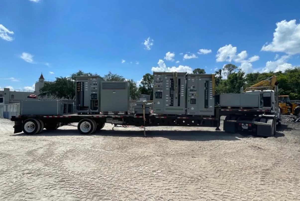
Discuss schedule at quotation and order review, because engineering approvals, component selection, design changes, and submittal turnaround can affect the production sequence. Ask which customer decisions are needed by each milestone and provide consolidated comments to reduce avoidable revision cycles. Short lead times may be available, but no delivery date should be assumed until the project scope, design, and current availability are reviewed. For nationwide shipment, coordinate the receiving window, unloading equipment, delivery access, storage conditions, and who will inspect the shipment on arrival. Outdoor equipment should be protected from damage and moisture while awaiting installation, following the manufacturer’s handling and storage instructions. Before shipment, confirm that the foundation, conduits, access route, and installation crew are ready; equipment arriving ahead of site readiness can create storage, handling, and schedule risks.