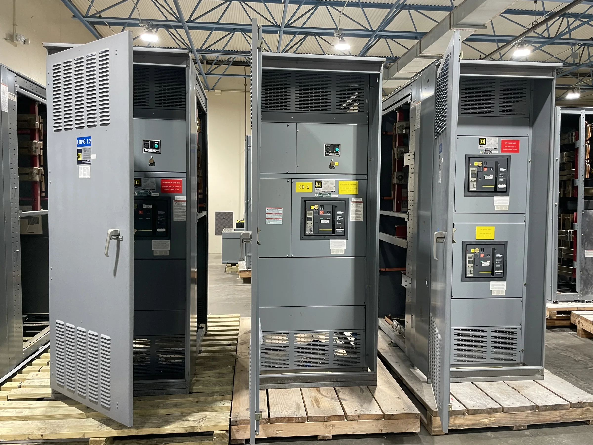
What Metal-Clad Switchgear Is Designed to Do
Metal-clad switchgear is a medium-voltage distribution assembly that groups circuit breakers, buses, instrument transformers, controls, and related components in grounded metal compartments. Barriers separate key components, so a fault in one compartment is less likely to expose equipment or personnel in adjacent sections than in an open arrangement. This compartmentalized construction also supports inspection and maintenance planning, but it does not eliminate arc-flash hazards or replace safe work procedures. The assembly receives power, switches and protects circuits, and distributes electricity to downstream transformers, motors, or other loads. It is not simply a larger low-voltage panelboard: its voltage class, insulation coordination, interruption duty, and application determine which equipment is appropriate. Confirming those fundamentals early prevents specifying a familiar-sounding product that cannot meet the system’s actual duties.
How It Differs from Metal-Enclosed Gear
The terms metal-clad and metal-enclosed are related, but they should not be treated as interchangeable specifications. Metal-clad gear generally uses separate grounded metal compartments for major primary components, including the circuit breaker and bus. Metal-enclosed switchgear is a broader category; its construction and internal barriers may differ by equipment type and applicable standard. Those distinctions affect access, maintenance procedures, component interchangeability, and how a project team evaluates internal separation. A buyer should compare the proposed construction against the governing project requirements rather than rely on the product name alone. Ask for the applicable standard, assembly arrangement, breaker configuration, and compartment details in the submittal. That documentation lets the engineer verify that the offered design matches the intended application, instead of discovering a construction mismatch during approval or installation.


Start with System Conditions and Protection Needs
Specify metal-clad switchgear from the electrical system outward. Useful inputs include nominal system voltage, frequency, available short-circuit current, grounding method, continuous load, source configuration, and the required protective-device functions. The project engineer must also coordinate breaker ratings and protective settings with upstream sources and downstream equipment; a breaker that fits physically may still be unsuitable for the system duty. Consider whether the lineup must support utility service, generator connections, motor feeders, tie breakers, or future expansion. Each function can affect compartment arrangement, control wiring, metering, and bus configuration. Requesting a quote with only a voltage and a breaker count leaves important assumptions unresolved. Provide a one-line diagram, equipment schedule, and known fault-current information where available, then identify open engineering items for confirmation before the design is finalized.
Plan the Lineup Around the Building
A sound electrical design still has to fit the actual electrical room and installation route. Record room dimensions, ceiling height, door and corridor clearances, floor conditions, cable trench or conduit locations, and the intended cable entry and termination approach. Front and rear access requirements depend on the selected arrangement and maintenance plan, so confirm them against the manufacturer’s drawings rather than assuming a standard clearance. Shipping sections may have to pass through a narrow doorway, turn in a corridor, or be moved with limited lifting access. These constraints can affect lineup segmentation, connection points, and the sequence of assembly at the site. Share architectural plans and site access notes during quotation and engineering review. Resolving a tight turn or cable-entry conflict on paper is generally easier than revising foundations or handling plans after equipment arrives.
Review Drawings, Ratings, and Scope Before Release
Before approving a purchase, align the quotation, technical specification, one-line diagram, and proposed drawings. Check that breaker functions, bus arrangement, metering, control power, relaying, communications, and spare provisions reflect the project documents. Confirm the intended voltage class and duty ratings, including the available fault current and any specified withstand or interruption requirements; exact ratings and applicability depend on the system and evaluated assembly. Clarify which items are included in the manufacturer’s scope and which are supplied or completed by others, such as protective relays, external cables, foundations, or site connections. Record deviations explicitly so reviewers can assess their impact instead of finding them in fine print. For low-voltage switchboard assemblies, UL 891 may be relevant when the project calls for an appropriately evaluated assembly; it is not a blanket certification for medium-voltage metal-clad switchgear.
Coordinate Manufacturing, Delivery, and Replacement Work
A U.S. manufacturer can discuss a custom build, American components, short lead-time options, and nationwide shipping, but the schedule and configuration must be confirmed for the specific order. Procurement teams should establish required submittal dates, approval milestones, factory scope, shipment destination, unloading responsibility, and any site receiving restrictions. A delivery plan should account for section size and weight, vehicle access, lifting equipment, storage conditions, and whether the electrical room will be ready to receive the lineup. Replacement or retrofit work adds interfaces with existing buses, cables, protection schemes, and controls; field dimensions and system records need review before compatibility is assumed. Plan outages and commissioning with qualified personnel, and perform electrical work only under appropriate de-energized conditions and established safety procedures. When requesting a quote, include the project schedule, drawings, site constraints, and known retrofit interfaces so engineering and delivery assumptions can be evaluated together.