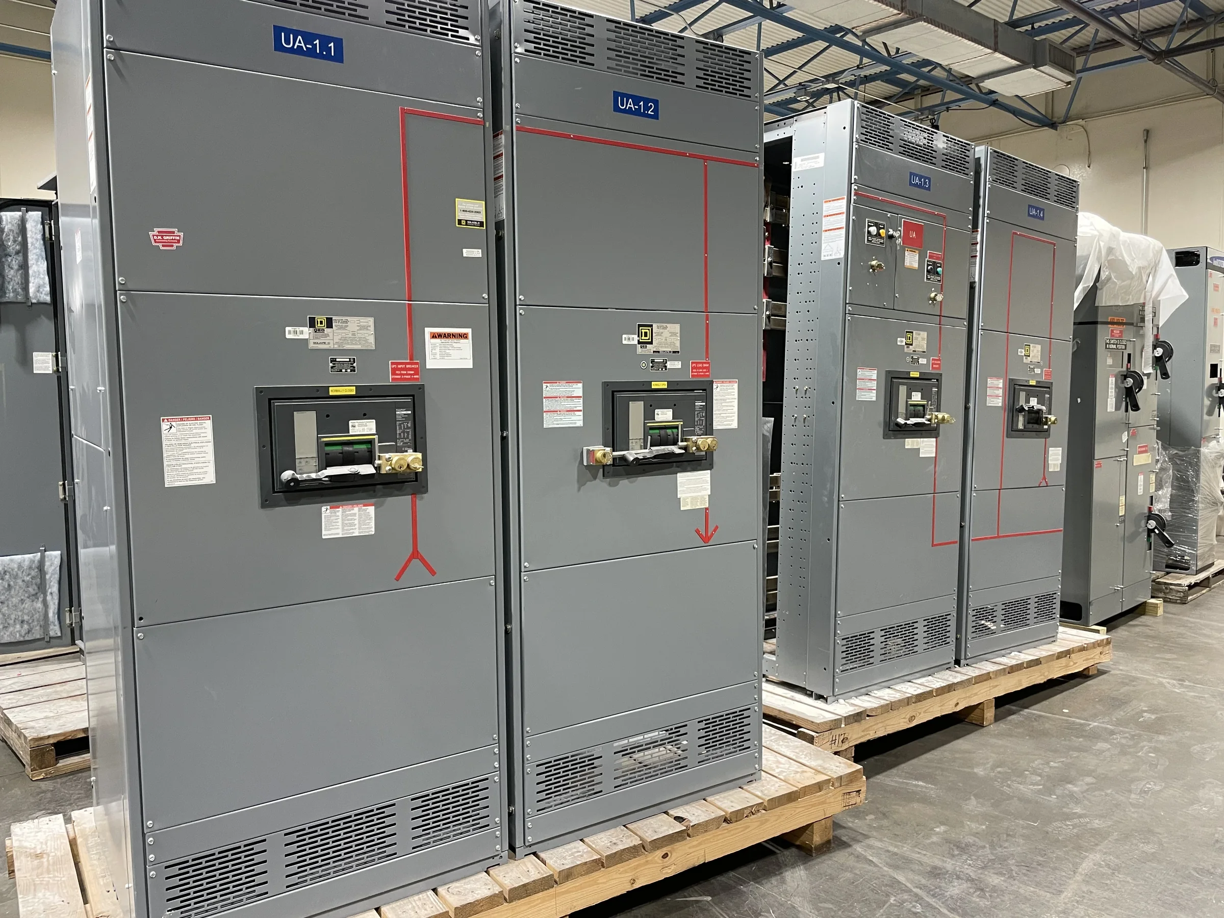
Define the Replacement Scope Before Requesting a Quote
Start by documenting what the existing lineup does, not just its nameplate rating. Record the equipment type, voltage, phase, frequency, bus arrangement, main and feeder devices, available fault-current information, and the loads served. Note whether the project replaces a complete switchboard or addresses a defined section, and identify any equipment that must remain in service. These details affect the proposed configuration, interfaces, and outage plan; a mismatch can leave feeders, controls, or downstream equipment without a workable connection. Share clear photographs, nameplate data, and current one-line diagrams when available. If records conflict with field conditions, flag the discrepancy rather than treating an old drawing as verified. Final ratings and compatibility require project-specific engineering review.
Translate Operating Requirements Into a Buildable Specification
A replacement specification should describe operating duties and interfaces alongside electrical ratings. Identify normal and emergency sources, transfer arrangements, metering and control functions, grounding provisions, protective-device requirements, and any communications or alarm connections. Explain which existing cables, conduit entries, interlocks, or monitoring systems must be retained, and which may change. Where coordination or arc-flash studies inform device selection, provide the current study documents and clearly identify assumptions that have changed. This context helps the manufacturer evaluate a new assembly around the application instead of relying on incomplete legacy labels. Applicable standards, device compatibility, and any requested evaluation or marking depend on the final design and scope. For low-voltage switchboard work, ask specifically whether UL 891 evaluation is applicable to the proposed assembly.


Check the Room, Access Route, and Connection Points
A lineup can be electrically suitable yet impractical to install if the room or delivery path cannot accommodate it. Measure available wall and aisle space, ceiling height, door openings, turning clearances, floor transitions, and the route from the unloading point to the equipment location. Record existing cable-entry directions, bus or duct connections, grounding points, and obstructions that may constrain the new arrangement. Also review working clearances and ventilation needs against the project design and applicable requirements; do not assume the existing installation establishes what is acceptable. Provide site plans, field dimensions, and images with a quote request, noting measurements that still need verification. Early review can reveal when sectional construction, revised placement, or a planned building modification should be considered before drawings are finalized.
Coordinate Drawings, Approvals, and Existing-System Interfaces
Before release for manufacture, establish who reviews the equipment drawings and which documents are needed for approval. A useful package may include a one-line diagram, elevations, layouts, wiring or control diagrams, device schedules, and connection details, as appropriate to the scope. Compare the proposed arrangement with field-verified feeder destinations, conductor entry, phase sequence, control wiring, and upstream and downstream equipment. Mark changes clearly so reviewers can distinguish confirmed requirements from open questions. Identify responsibility for engineering studies, permits, utility coordination, and acceptance procedures rather than assuming they are included in an equipment quote. This review matters because an unnoticed interface difference can delay installation or require field changes. Resolve comments and document approved revisions before production; the final deliverables and review process should be agreed for each project.

Build a Realistic Schedule Around Shutdown and Site Readiness
Replacement timing depends on more than the manufacturing window. Align drawing review, design decisions, component availability, production planning, shipping, site preparation, and the permitted outage period. Ask for a project-specific schedule and identify which dates are targets, which depend on approvals, and what could change if the scope or selections are revised. Meanwhile, confirm who will isolate the existing equipment, prepare foundations or cable routes, arrange qualified installation support, and coordinate required inspections. Electrical work must be planned and performed with equipment de-energized under applicable safety procedures; an outage should not be treated as optional simply because the new assembly is ready. A written responsibility matrix and contingency plan help facility teams coordinate production continuity without turning an estimated delivery period into a guarantee.
Plan Shipping, Receiving, and the Changeover Handoff
Nationwide shipment makes receiving coordination part of replacement planning, not an afterthought. Confirm the delivery address, site access limits, unloading equipment, receiving hours, storage conditions, and the people authorized to inspect and sign for the shipment. Match the shipping configuration to the route and installation plan, and clarify how sections will be identified and handled using the manufacturer’s project documents. Before the outage, reconcile approved drawings, labels, device schedules, and connection requirements with the site’s installation package. After installation, define the records the owner needs, such as final drawings, equipment documentation, and test or inspection records produced under the project scope. These handoff details support traceability and maintenance. Exact packaging, transport arrangements, documentation, and availability should be confirmed in the project quote and submittal.