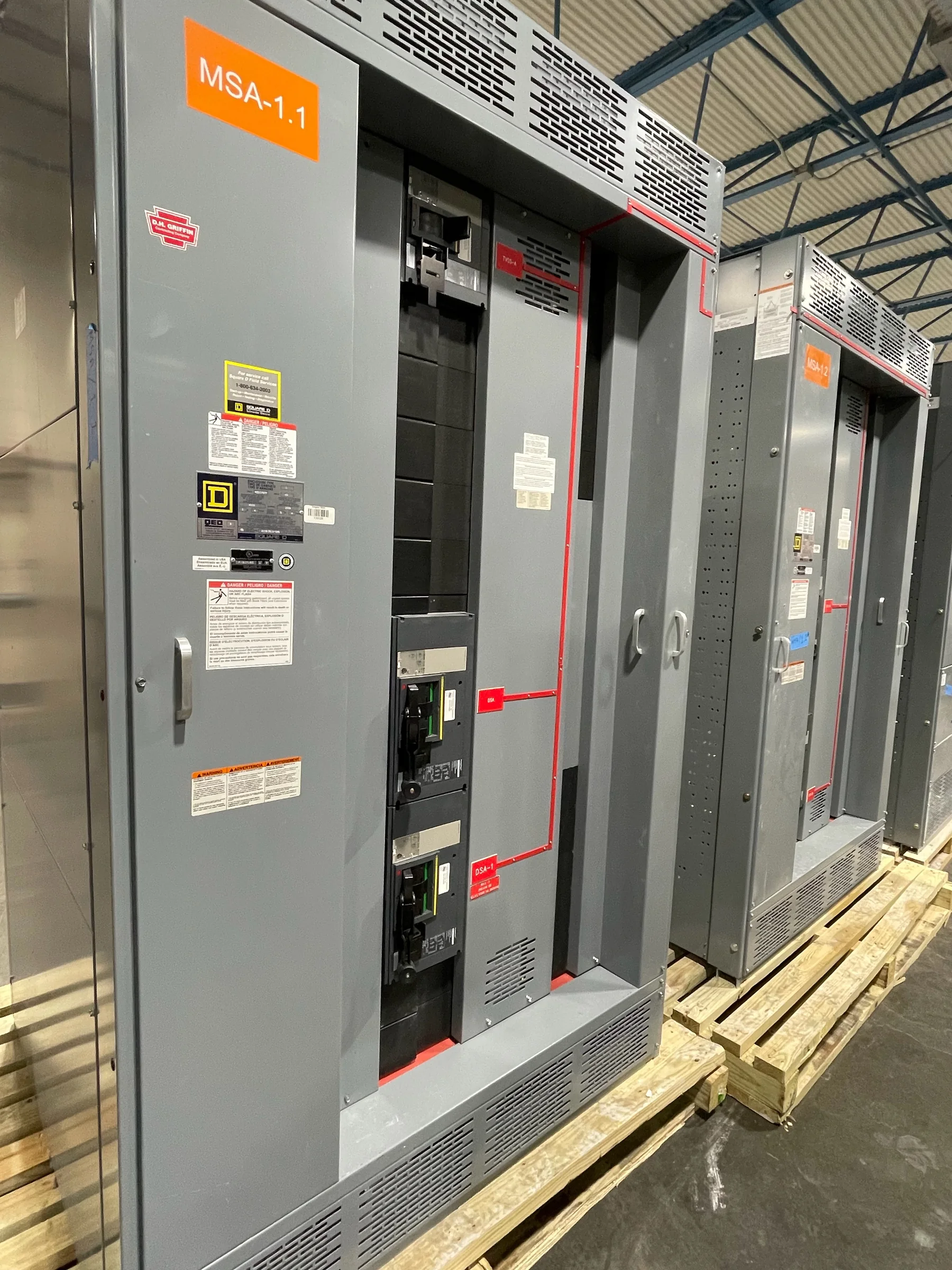
Define the Substation’s Electrical Scope
Start procurement by identifying what the substation switchgear must connect, control, and protect—not simply by choosing a voltage class. Gather the one-line diagram, utility service information, transformer data, available fault-current study, grounding approach, and intended operating sequence. These documents help engineers determine whether the project calls for medium-voltage metal-enclosed switchgear, low-voltage distribution equipment, or coordinated assemblies serving different parts of the installation. They also reveal interface questions such as incoming cable entry, transformer termination, bus connections, metering, and protective-device coordination. An early mismatch can force redesign of cable routes, protection settings, or the substation layout after equipment is specified. Confirm requirements with the responsible electrical engineer and utility; final ratings, configuration, and standards applicability depend on the project.
Match Equipment to the Site and Duty
Substation conditions influence enclosure design and component selection as much as the single-line diagram does. Document indoor or outdoor placement, ambient temperature range, elevation, moisture exposure, airborne dust or corrosive contaminants, and the equipment’s accessibility for inspection. Consider whether the switchgear serves a utility interface, a plant distribution system, renewable generation, or a critical facility, since operating practices and consequences of an interruption differ. Available fault current, system grounding, switching duty, load characteristics, and protection philosophy must be evaluated by qualified project personnel rather than inferred from a general product description. These details matter because an assembly suited to a clean electrical room may not be appropriate for an exposed site. Confirm enclosure, ratings, and environmental suitability against project documents before release.


Coordinate Protection, Controls, and Interfaces
Protection and control requirements should be resolved alongside the switchgear arrangement, not left until installation. Identify the relays, metering, instrument transformers, control power, communications, interlocks, and remote signals required by the project, then assign responsibility for settings, wiring diagrams, and interface testing. A utility may have specific requirements for metering, isolation, or communications; a facility may need alarms and status points integrated with its supervisory system. Incomplete interface information can delay engineering approval or leave field teams without a clear point-to-point wiring plan. Request review drawings early and have the responsible engineer verify coordination with upstream and downstream devices. Relay functions, communications protocols, and integration scope are project-specific, so confirm compatibility rather than assuming that a listed option will match existing equipment.
Plan Replacement and Retrofit Work Carefully
Replacing substation switchgear in an operating facility requires a plan for both the new equipment and the transition from existing gear. Record existing manufacturer and model information where available, bus and cable termination details, room dimensions, access openings, control wiring, and protective-device arrangements. Compare these conditions with proposed drawings before approving fabrication: a new assembly may fit electrically yet require a different cable approach, foundation, aisle clearance, or conduit route. Establish the outage window, temporary operating arrangements, removal sequence, and testing responsibilities with the facility team and qualified contractors. All work must follow an approved safety and isolation plan; equipment is not made safe merely by a schedule or design decision. For retrofit projects, verify every interface in the field and resolve discrepancies before equipment release.
Review Drawings, Standards, and Submittals
A complete submittal review gives procurement, engineering, and construction teams a shared basis for accepting the equipment. Check the proposed one-line and arrangement drawings against the approved design, including equipment boundaries, compartment layout, cable access, bus interfaces, control schematics, nameplate information, and specified accessories. Document comments clearly and identify which party will resolve each open item; unclosed assumptions can become expensive changes after fabrication begins. Specify required standards and evaluations by equipment type and application. UL 891 applies to appropriately evaluated low-voltage switchboard assemblies; it should not be treated as a blanket certification for medium- or high-voltage substation equipment. Confirm the exact assembly, labeling, and documentation requirements for the project rather than assuming every configuration carries the same listing or approval.
Align Build Timing, Shipping, and Site Readiness
Discuss schedule and delivery constraints with the U.S. manufacturer while the specification is being developed. Custom configuration, design approvals, component availability, and requested documentation can all affect the project timeline, so request a current schedule for the defined scope instead of relying on a generic lead-time statement. Coordinate shipping method, receiving hours, unloading equipment, staging area, route to the electrical room, and protection from weather or site damage. Long or heavy sections may be difficult to move through existing doors, corridors, or crane access points; verify the handling plan against the shipping configuration and site drawings. Nationwide shipping is an available offering, but transit and site logistics are project-specific. Before dispatch, confirm approved drawings, delivery contacts, receiving readiness, and any sequencing needed to keep installation work coordinated.