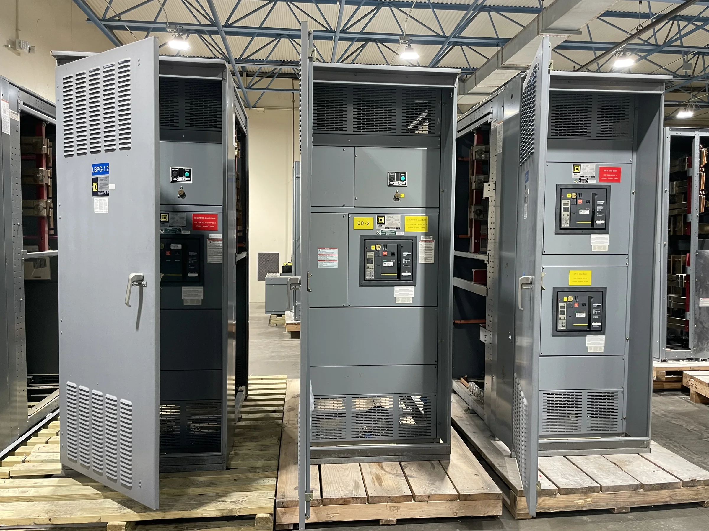
What a Motor Control Center Does
A motor control center (MCC) is a grouped assembly of vertical sections that distributes power to motors and houses their associated control and protection equipment. Individual compartments, often called buckets or units, can be configured for particular loads and operating needs. Depending on the design, an MCC may include motor starters, disconnecting means, overload protection, variable-frequency drives, soft starters, control power, and metering. The important distinction is that an MCC organizes multiple motor circuits in a common assembly; it is not simply a panelboard with a different name. For engineers and procurement teams, this affects the one-line diagram, feeder sizing, protection coordination, and space planning. The assembly’s configuration and ratings must be selected for the actual system and application.
Where MCCs Fit in an Electrical System
MCCs are commonly used where a facility has several motors whose power and control connections benefit from centralized organization. Examples include pumps, fans, compressors, conveyors, and process equipment, though a suitable arrangement depends on each load and the operating environment. The project team should identify which motors belong in the center, which require local controls, and whether any loads need speed control or coordinated sequencing. Those decisions influence the number and type of units, incoming and distribution arrangements, control wiring, and available space. They also affect maintenance access: concentrating equipment can simplify circuit identification, but it can create an operational bottleneck if essential loads share an assembly without a suitable continuity plan. Documenting process relationships early helps avoid late design changes.


Specifications That Shape the Assembly
An MCC specification should describe the electrical system and the required functions, not merely request a nominal cabinet size. Useful inputs include system voltage and frequency, available fault current, incoming feeder arrangement, motor horsepower and full-load current, starting method, control voltage, and the intended protection and monitoring functions. Engineers also need to define environmental conditions, enclosure requirements, cable entry, and any interface with the facility’s control system. These details help determine whether units and sections can be arranged as intended and whether the assembly aligns with the project’s electrical design. Applicable standards and evaluation requirements must be established for the specific equipment; UL 891 applies to appropriately evaluated low-voltage switchboard assemblies and is not a blanket designation for MCCs or higher-voltage equipment.
Layout, Access, and Installation Constraints
A workable MCC layout accounts for the route from receiving to the electrical room as well as the final footprint. Before release, verify door and corridor clearances, turning space, floor capacity, room access, ceiling height, ventilation, and the planned cable or bus connections. Confirm the manufacturer’s shipping and handling configuration against the site route; sections that fit in the room may still be difficult to move through a doorway or around a tight turn. Working clearances and access for operation and maintenance must be coordinated with applicable codes and project requirements. Cable-trench position, conduit stub-ups, overhead obstructions, and neighboring equipment can affect section placement. Resolving these constraints before fabrication reduces field modifications, schedule disruption, and the risk that installed equipment blocks safe access.
Documents to Align Before Release
A complete submittal review connects the equipment schedule to the plant’s operating needs. Check the one-line diagram, MCC lineup and elevation drawings, unit schedule, elementary or wiring diagrams, control schematics, connection details, and bill of materials against the design basis. Confirm that each motor tag maps to the correct unit and that starter type, overload range, disconnect arrangement, control interface, and spare-space expectations are clear. A mismatch between a motor list and control narrative can lead to a bucket that cannot perform the required sequence, even if its basic electrical rating is suitable. Procurement teams should also identify review responsibilities, required drawing revisions, and interface points with field devices, PLCs, and upstream protection. Resolve comments before approved-for-manufacture release.
Timing, Delivery, and Project Coordination
MCC timing depends on how quickly requirements are settled, the selected configuration, component availability, engineering review, and the project’s shipping and installation sequence. A U.S. manufacturer can discuss custom builds, American components, short lead times, and nationwide shipping, but exact availability and delivery dates are project-specific and should be confirmed in the quotation and order documents. Share the needed-on-site date, receiving hours, unloading method, storage conditions, and restrictions on truck access early. Coordinate shipment with room readiness and the electrical contractor’s installation plan; prolonged outdoor storage or a blocked delivery route can damage equipment or disrupt work. Before energization, qualified personnel must complete required installation checks and follow the approved safety procedures. Clear ownership for receipt, inspection, and discrepancy reporting helps keep the project moving.