Start With the Equipment’s Function, Not Its Name
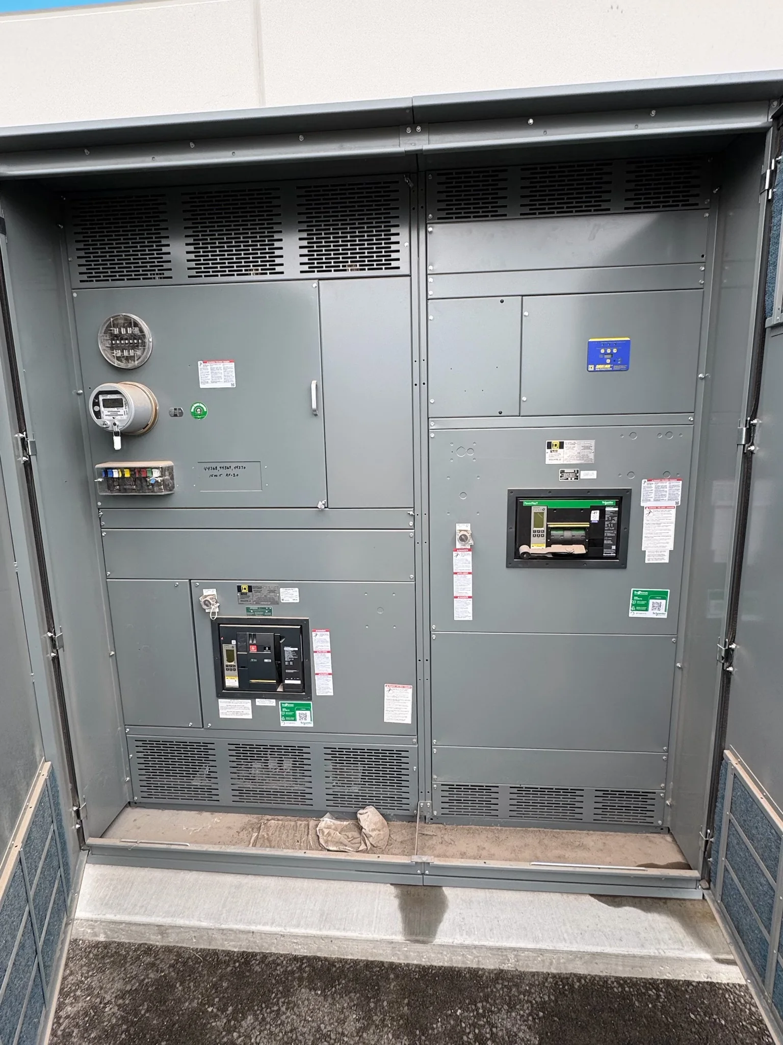
“Switchgear” and “switchboard” are often used loosely, but the distinction affects the equipment you should specify. A switchboard is generally a low-voltage assembly that distributes power from an incoming source to multiple circuits, using devices such as circuit breakers or fusible switches. Switchgear is a broader term for assemblies that switch, protect, and isolate electrical circuits; in many project specifications, it refers to equipment with defined protective-device and isolation features and may serve low-, medium-, or high-voltage applications. Terminology varies among standards, manufacturers, and project teams, so the label alone is not a sufficient basis for selection. Describe the system voltage, sources, loads, fault conditions, operating needs, and required protection. That functional description helps prevent mismatched quotes and unnecessary redesign.
Compare Ratings, Protection, and System Coordination
The practical comparison starts with the electrical system and the consequences of a fault. Confirm nominal voltage, frequency, continuous current, available short-circuit current, and the required withstand or interrupting ratings for the complete assembly and its devices. Those values are not interchangeable: a breaker’s interrupting rating does not, by itself, establish the assembly’s short-time withstand capability or prove coordination with upstream and downstream protection. Review the one-line diagram, utility or source data, transformer information, and protection study where available. Selectivity, ground-fault protection, arc-energy mitigation, and maintenance practices can influence the design and operating sequence. An engineer should resolve these requirements for the project rather than infer them from “switchgear” or “switchboard.” Final ratings and compliance depend on the specific design and applicable evaluation.


Account for Space, Access, and Installation Conditions
A suitable lineup must fit the actual electrical room and the route from the unloading point to its final position. Compare the proposed equipment’s footprint, height, sections, cable-entry arrangement, working clearances, and access for inspection or component replacement with verified site dimensions. Door swings, structural openings, overhead obstructions, floor loading, and the ability to maneuver sections can turn a nominally compatible design into an installation problem. Indoor or outdoor exposure, ambient conditions, contamination, and ventilation also shape enclosure and equipment choices; project-specific conditions should be documented rather than assumed. Coordinate these details with the electrical contractor, facility team, and equipment manufacturer before approving drawings. Early review can reveal whether a lineup needs a different arrangement or whether the room, conduit plan, or delivery method needs adjustment.
Prepare a Quote Package That Supports a Reliable Design
A useful request for quotation lets manufacturers compare the same requirements instead of filling gaps with different assumptions. Include the current one-line diagram, load schedule, system voltage, source and transformer data, available fault-current information, protection or coordination requirements, and the intended equipment location and environment. Identify required incoming and outgoing configurations, metering, control power, communications, interlocks, spare provisions, and any specified standards or project documents. Mark known constraints such as cable landing space, conduit locations, room access, and required shutdown windows. If information is still being developed, label it preliminary and list what remains open. This gives the manufacturer a basis to identify questions, clarify exclusions, and prepare a project-specific proposal. It also reduces the risk that a low initial price reflects omitted devices or unresolved scope.
Plan Schedule Around Submittals, Approvals, and Dependencies
Equipment timing is more than the quoted manufacturing window. The project schedule also depends on complete input data, drawing preparation, customer and engineer review, approved submittals, component availability, manufacturing, inspection, and readiness to receive the shipment. Custom configurations or late changes can affect that sequence, so ask what information is needed to begin and which milestones the proposal assumes. Confirm how revisions are handled, what documents will be provided for review, and whether approval dates are tied to the construction schedule. A U.S. manufacturer may offer short lead times, but no delivery period should be treated as guaranteed without a project-specific confirmation. Procurement teams should compare proposals on scope, assumptions, and stated schedule basis—not on a single headline estimate—and keep the site team informed about changes.
Coordinate Delivery, Startup, and Compliance Records
Before release, align the shipment plan with site access, receiving capacity, storage conditions, unloading equipment, and the installation sequence. Confirm delivery location, section handling requirements, packaging expectations, and who will inspect the shipment and report damage or shortages. Nationwide shipping does not eliminate project-specific coordination: a restricted dock, limited laydown area, phased construction, or scheduled outage may require careful timing. Collect the final approved drawings, device schedules, wiring diagrams, operating and maintenance information, and applicable test or compliance documentation needed by the owner and installer. For low-voltage switchboard assemblies, UL 891 may be relevant when the assembly is appropriately evaluated; it should not be assumed to apply to every product or to medium- or high-voltage equipment. Verify the specified standard, evaluation, and documentation for the exact assembly before purchase.