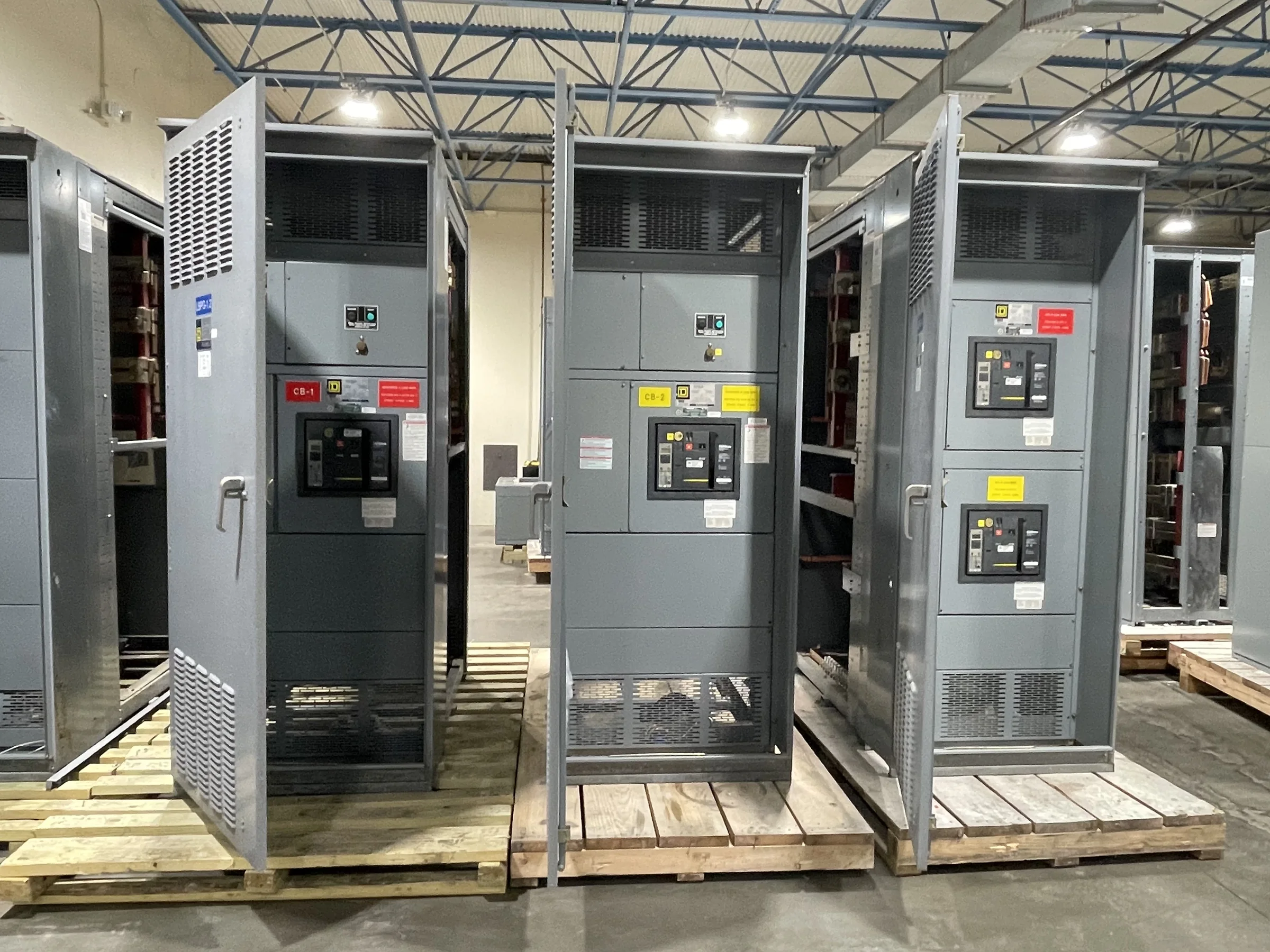
What a Switchgear Busbar Does
A busbar is a conductive bar or formed conductor that carries electrical power between incoming sources, circuit breakers, and outgoing feeders inside switchgear. Its job is not simply to connect components: it must carry the intended current and withstand the electrical and mechanical stresses expected in the assembly. Material, cross-section, support spacing, joints, and enclosure arrangement all affect performance. Copper and aluminum are common choices, but the appropriate material depends on the design, connection interfaces, project requirements, and evaluated assembly. For procurement teams, the practical question is how the bus system fits the complete equipment lineup—not whether one material is universally better. Confirm the one-line diagram, system voltage, available fault information, and intended loads before comparing proposals.
Main Bus, Feeder Bus, and Grounding Paths
The main bus distributes power along a switchgear section, while feeder connections branch power to individual circuits. A vertical or riser bus may connect devices arranged in separate compartments, depending on the equipment design. The equipment grounding path serves a different purpose: it provides a fault-current return path and bonds accessible metal parts as required by the design. These paths should not be treated as interchangeable, and a grounding conductor is not a substitute for a properly designed neutral where the system requires one. Review the one-line and equipment arrangement together to verify source, feeder, neutral, and grounding needs. This is especially important when replacing an existing lineup, where field labels or older drawings may not match current circuit use.


Current, Fault Duty, and Temperature Rise
Busbar selection must account for continuous current as well as the short-circuit stresses the assembly may encounter. A system’s available fault current, protective-device characteristics, and equipment configuration influence the required withstand capability; a bus ampere rating alone does not establish suitability. Heat also matters. Ambient conditions, enclosure construction, ventilation, adjacent heat sources, and the number and loading of connected devices affect temperature rise. Engineers should provide the manufacturer with load expectations, system data, and known site conditions so the proposed assembly can be evaluated as a complete design. Do not assume a rating transfers from a similar-looking lineup or applies to every configuration. Final ratings, applicable standards, and evaluation scope are project-specific and should be confirmed in the approved submittals.
Joints, Supports, and Connection Details
Bus joints are potential sources of resistance and localized heating if contact surfaces, hardware, alignment, or assembly practices are unsuitable. Bus supports must also maintain the intended spacing and resist forces associated with fault conditions. These details matter during both new construction and replacement work: field modifications, mismatched connection patterns, or unsupported extensions can undermine the intended assembly design. Before ordering, document the required bus arrangement, incoming and outgoing cable or busway interfaces, phase sequence, and any transition sections. For retrofit projects, verify dimensions and connection locations against field measurements rather than relying only on legacy drawings. Installation and inspection should follow the equipment manufacturer’s instructions and approved project documents, with the equipment de-energized and made safe before work begins.
Documents to Confirm Before Ordering
A clear procurement package reduces the chance of receiving equipment that meets the electrical intent but conflicts with the site. Useful inputs include a current one-line diagram, load and circuit schedules, system voltage and frequency, available fault-current information, incoming-source details, and the desired lineup arrangement. Add room dimensions, access routes, cable-entry direction, conduit locations, working clearances, and any known environmental constraints. Identify required controls, metering, communications, and coordination with existing protective devices. The manufacturer’s submittals should show the proposed configuration and identify assumptions, exceptions, and project-specific ratings for review before release to production. Where UL 891 applies, confirm that the particular low-voltage switchboard assembly is appropriately evaluated; that designation does not establish a blanket listing for medium- or high-voltage equipment.
Timing, Shipment, and Site Readiness
Busbar design is tied to the complete switchgear configuration, so late changes to feeder quantities, device frames, cable entry, or room layout can affect engineering, approval, and manufacturing schedules. Discuss required dates early, and ask the manufacturer to identify the information needed to keep the project moving; lead times and availability depend on the scope and are not guaranteed by a general short-lead-time offering. Nationwide shipment also calls for practical coordination: confirm the receiving location, unloading responsibility, delivery access, staging space, and whether the route can accommodate the equipment sections. Before shipment, align the approved drawings with site conditions and installation sequencing. A prepared room, verified access path, and coordinated receiving plan help prevent avoidable delays after the equipment arrives.