Define the Control-Wiring Scope Before Release
Switchgear control wiring connects protective devices, meters, operator controls, alarms, and external systems so the equipment performs its intended functions. Before a new assembly is released for manufacture, identify which circuits belong inside the switchgear and which terminate at field devices or a separate control panel. Provide the one-line diagram, elementary diagrams, device schedule, control-voltage requirements, and a clear list of required indications and interlocks. These documents help resolve whether a signal is hardwired, provided through a communications interface, or reserved for future use. Ambiguity can lead to missing terminals, incompatible devices, or late design revisions. A U.S. manufacturer can review the project requirements with the procurement and engineering teams; final scope and compatibility remain specific to the application.
Coordinate Schematics, I/O, and Device Selection
A useful control-wiring package shows how each device operates, not merely where it sits in the lineup. Confirm breaker close and trip functions, status contacts, protective-relay inputs and outputs, metering signals, alarms, and any control power supplied by the customer. For PLC, SCADA, or building-management connections, agree on signal names, contact states, terminal references, and communication responsibilities with the system integrator. The distinction matters: a status point expected as a dry contact cannot be assumed to arrive through a network gateway, and differing naming conventions can complicate commissioning. Device selections, ratings, and interface details should be checked against the approved drawings and equipment requirements. Keep the point list and elementary diagrams aligned as revisions are issued.


Plan Terminations for Installation and Future Service
Terminal placement and wire identification influence how quickly an installer can connect field conductors and how safely a technician can trace a circuit later. Provide the expected cable-entry direction, field-wire size range, termination method, and any access or segregation constraints, subject to design review. Identify circuits that must land at specific compartments or terminal blocks, particularly when control cables enter through a congested trench or overhead tray. Clear labels and consistent cross-references reduce the chance of a control conductor being landed on the wrong point. They also make drawing updates and troubleshooting more manageable. When planning retrofit interfaces, document existing terminal assignments and cable destinations rather than relying on old markups. Confirm final termination details against approved drawings and the delivered equipment.
Address Site Conditions and Delivery Sequence
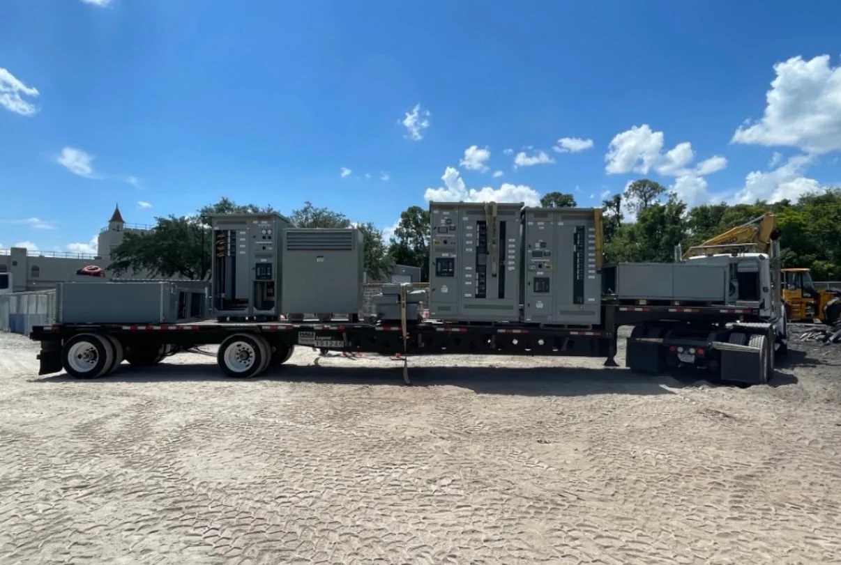
Control wiring decisions can affect equipment layout, cable routing, and the order in which sections are installed. Share room dimensions, door and aisle clearances, conduit or tray locations, floor openings, and the planned path from unloading point to final position. These constraints matter because a lineup that fits electrically may still be difficult to move through a doorway or connect after neighboring equipment is installed. For multi-section assemblies, coordinate shipment breakdown, receiving access, storage conditions, and the sequence for setting and joining sections with the project team. Nationwide shipping supports projects across the United States, but transport arrangements and timing depend on the shipment and destination. Confirm site readiness, delivery coordination, and any handling limits before scheduling a release.

Review Timing, Revisions, and Procurement Inputs
A realistic manufacturing schedule begins with complete, coordinated project information—not an assumed standard lead time. Identify the required ship window, approval milestones, drawing-review contacts, long-lead devices, and any customer-furnished components. If protection settings, communications requirements, or external interlocks remain undecided, flag them as open items and agree on how they will be resolved before design approval. Late changes can affect wiring diagrams, terminal assignments, material selection, and manufacturing sequence. Ask for a project-specific quotation that states the proposed scope, exclusions, documentation, and delivery assumptions; verify availability and timing during review. The manufacturer offers custom builds and short lead times, but neither establishes a guaranteed date for every configuration. Keep procurement, engineering, and the site team working from the same revision.
Use Drawings and Testing Records for Turnover
Closeout information should let the owner understand what was built and how its control circuits are intended to function. Specify the required drawing format and turnover set, including final elementary and connection diagrams, terminal plans, device data, and approved revision records where applicable. If the project requires inspection or functional checks, define the requested scope and acceptance criteria early; the actual test plan depends on the design and contract. This distinction prevents a quotation from being interpreted as including unrequested verification. UL 891 may apply to appropriately evaluated low-voltage switchboard assemblies, but it is not a blanket certification for all switchgear or voltage classes. Confirm applicable standards, evaluation scope, and labeling requirements for the specific assembly. Provide the site team with current documents before installation and commissioning.