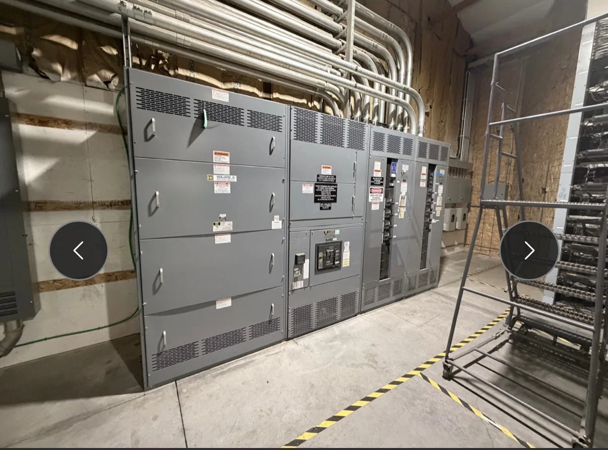
Define the Modernization Scope Before Selecting Equipment
A switchgear modernization project in Pearland should begin with a clear boundary between equipment being replaced and equipment expected to remain in service. Document the existing lineup’s function, voltage, phase, frequency, bus arrangement, available fault-current information, protective devices, metering, and connected loads. Record nameplate data and note obsolete, damaged, or undocumented components, but do not assume a new assembly can connect directly to an existing section. Differences in bus geometry, cable entry, control voltage, grounding, or protection can affect both compatibility and outage scope. Share one-line diagrams, photographs, and field measurements with the manufacturer so the proposed equipment can be reviewed against actual conditions. Exact ratings, interfaces, and applicable standards must be confirmed for the project, not inferred from the old lineup alone.
Match the Equipment to the Electrical System
Specify new equipment against the system’s operating requirements rather than treating modernization as a like-for-like cabinet swap. Engineers and procurement teams should confirm normal and emergency sources, load characteristics, expected expansion, fault-duty requirements, protective coordination, metering needs, and the intended switching arrangement. Where the project involves low-voltage switchboard assemblies, UL 891 may be relevant when the assembly is appropriately evaluated; it is not a blanket certification for medium- or high-voltage equipment. Identify the governing project standards and required submittals early, then ask the manufacturer to clarify which proposed assembly and options meet the documented scope. A change in feeder size, source capacity, or protection strategy can affect equipment selection and downstream coordination, so the owner’s engineer should review design assumptions before purchase.


Plan Around Pearland’s Heat, Humidity, and Site Conditions
Pearland’s Gulf Coast setting makes environmental conditions worth documenting for the equipment location, particularly where gear will sit in a non-conditioned electrical room, outdoor enclosure, or area exposed to moisture and contaminants. Provide the manufacturer with the installation location, ambient conditions, ventilation details, enclosure location, and any known exposure to dust, chemicals, washdown, or corrosion. These details can influence enclosure construction, space for heat dissipation, and component choices, but suitability must be evaluated for the actual application. Also check whether the room has adequate working clearances, door swing, access routes, housekeeping pads, and space for cable bending and terminations. A lineup that fits a drawing may still be difficult to install or maintain if room dimensions and access constraints are not verified in the field.
Coordinate Timing, Submittals, and the Outage Window
Modernization schedules depend on more than the equipment build period. Establish when the facility needs approved drawings, when field dimensions can be verified, what reviews must be completed, and how the planned outage fits production or building operations. A short lead time may be available for some custom builds, but timing depends on the final design, component availability, approvals, and project-specific scope; obtain a current schedule for the specified assembly rather than relying on a general estimate. Keep the existing equipment in service until the replacement plan, site readiness, and authorized outage are coordinated. The installation sequence should define responsibilities for removal, rigging, connection, testing, and return to service. Any work involving electrical equipment must be planned and performed under applicable safety procedures, with de-energized work required where appropriate.
Prepare Drawings and Field Information for a Clean Installation
Useful procurement documents help prevent late changes that can disrupt both fabrication and site work. Include the latest one-line diagram, load and feeder schedules, equipment elevations, room plan, cable and conduit entry information, control schematics, protection requirements, and the applicable specifications. Mark uncertain dimensions or undocumented circuits explicitly rather than presenting estimates as verified facts. For replacement work, identify which existing conduits, conductors, controls, and external interfaces are intended to remain, and ask the project team to confirm their condition and compatibility. Review manufacturer submittals for dimensions, access, connection points, ratings, and scope boundaries before releasing the equipment for production. Clear comments and an approved drawing set give the shop and installation team a common reference, reducing the risk of mismatched openings, missed interfaces, or avoidable field modifications.
Coordinate Delivery and Commissioning at the Pearland Site
Nationwide shipping can support a Pearland project, but delivery planning should reflect the destination’s actual access and handling conditions. Confirm truck approach, gate and dock restrictions, unloading equipment, delivery hours, laydown space, weather protection, and the route from the receiving point to the electrical room. Large or heavy sections may require a planned rigging path, and the receiving team should know how the shipment is divided and what must be inspected on arrival. Before placing an order, align the requested delivery window with site readiness and the approved outage plan; transport timing and availability are project-specific, not guaranteed by a general lead-time statement. Closeout planning should also identify required drawings, operating information, inspection records, and commissioning responsibilities so the owner receives the documentation needed to maintain the new distribution equipment.