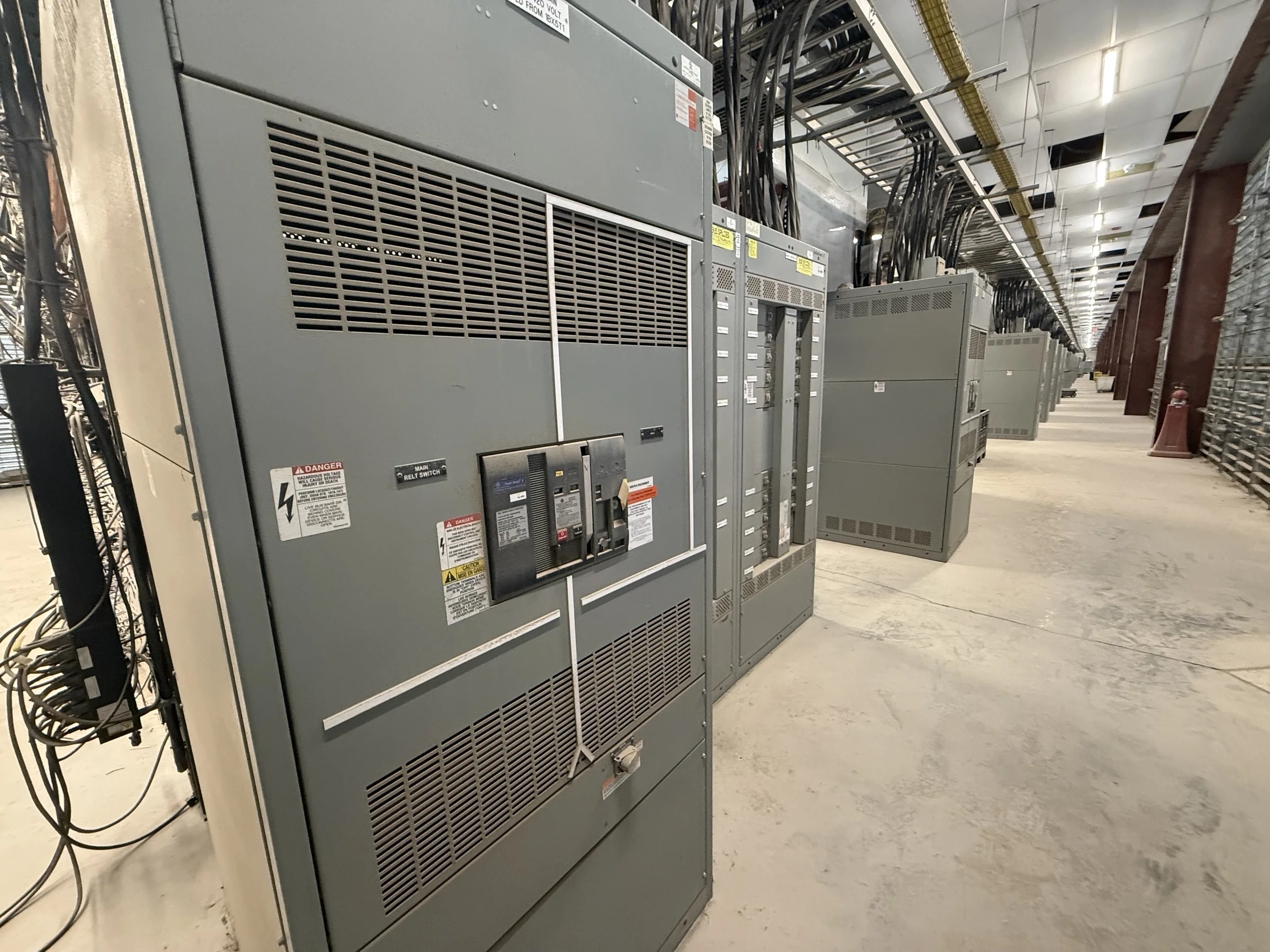
Modernization Starts with the Existing Distribution Scheme
In The Woodlands, a switchgear modernization project may involve replacing aging distribution equipment while keeping occupied offices, healthcare spaces, commercial facilities, or industrial operations supplied. Begin with the one-line diagram and confirm how utility service, transformers, tie breakers, generators, and downstream feeders actually connect; field conditions may differ from old drawings. That distinction matters because a new lineup must suit the intended operating arrangement, not simply match the old cabinet’s footprint. Record system voltage, available fault-current information, grounding method, bus and feeder requirements, protective-device functions, and any required future capacity. A U.S. manufacturer can build new equipment around a project specification, but final design, ratings, and compatibility need engineering review against verified site data and applicable project requirements.
Define the Replacement Scope Before Requesting a Quote
A useful quotation package distinguishes equipment supply from demolition, installation, testing, and commissioning, which may be assigned to different contractors. Identify whether the project calls for a complete new lineup, phased replacement, or equipment intended to connect with retained transformers, conductors, or downstream gear. Existing gear’s make and model, compartment dimensions, cable-entry direction, termination space, and access clearances help reveal interface constraints, but do not by themselves establish compatibility. Include the desired bus configuration, breaker or switch functions, metering, control power, auxiliary contacts, communications needs, and spare provisions where known. Ask the manufacturer to identify assumptions and open questions in its proposal. A clear scope helps procurement compare equivalent bids and reduces the risk of late changes when drawings are reviewed.


Resolve Ratings, Protection, and Standards by Application
Electrical ratings must follow the system study and the equipment’s intended application; a familiar rating from the existing lineup is not proof that it remains suitable after a service or transformer change. Confirm voltage class, continuous current, short-circuit duty, withstand requirements, and protective-device coordination with the responsible engineer and utility as applicable. Review breaker trip functions, ground-fault protection, metering accuracy needs, control schemes, and interfaces to building or plant systems as distinct requirements. UL 891 applies to appropriately evaluated low-voltage switchboard assemblies; it should not be represented as a blanket listing for medium- or high-voltage equipment. Specify the required standard, evaluation, and labeling for the actual assembly, then verify them in approved submittals. Ratings, standards, and labeling depend on the final design and project.
Plan Site Interfaces and Installation Constraints
The Woodlands area includes developed commercial corridors, campuses, and sites where delivery access, tenant activity, and utility coordination can affect installation sequencing. Measure the route from receiving point to electrical room, including door openings, turns, floor loading, overhead obstructions, and any elevator or rigging limits. Compare those constraints with the proposed lineup’s shipping sections and handling provisions before equipment is released. Confirm cable approach, conduit locations, bend space, working clearances, ventilation, environmental conditions, and room access with the installing contractor. If existing equipment serves critical loads, develop the outage and temporary-power plan with the facility team and qualified electrical professionals; do not assume a simple swap can avoid an outage. Early coordination helps prevent an assembly from arriving before the site can safely receive or install it.
Use Submittals to Close Design and Procurement Gaps
Before fabrication, review the equipment submittal against the project specification, one-line diagram, panel schedules, and actual field measurements. Check lineup dimensions, section arrangement, bus details, incoming and outgoing connections, breaker types, protective settings responsibilities, metering, control wiring, labels, and any required communications points. Mark deviations explicitly so the engineer of record can resolve them rather than letting assumptions become field changes. A document register should identify who approves drawings, who supplies utility data, and who confirms interfaces with retained equipment. Request the applicable documentation for the proposed assembly, including drawings and product information needed for installation and maintenance; do not presume a particular test report or certification unless specified and confirmed. Procurement should also clarify quotation validity, scope exclusions, shipping terms, and schedule dependencies in writing.
Coordinate Timing, Delivery, and Turnover
Discuss schedule early with the manufacturer, installer, and facility representative: drawing approval, release of complete technical data, component selection, design changes, and site readiness can all influence the production and delivery plan. Short lead times may be available for some custom builds, but no duration should be assumed until the specific configuration and current component availability are reviewed. Nationwide shipping supports projects in The Woodlands, yet the site still needs a confirmed receiving window, unloading equipment, staging location, and protection from weather or construction traffic. Align delivery with room completion and installation resources rather than using arrival as the only milestone. Turnover planning should identify approved drawings, final settings and coordination records, operating and maintenance information, and the responsible parties for inspection and commissioning. Confirm all dates and deliverables against the project’s actual scope.