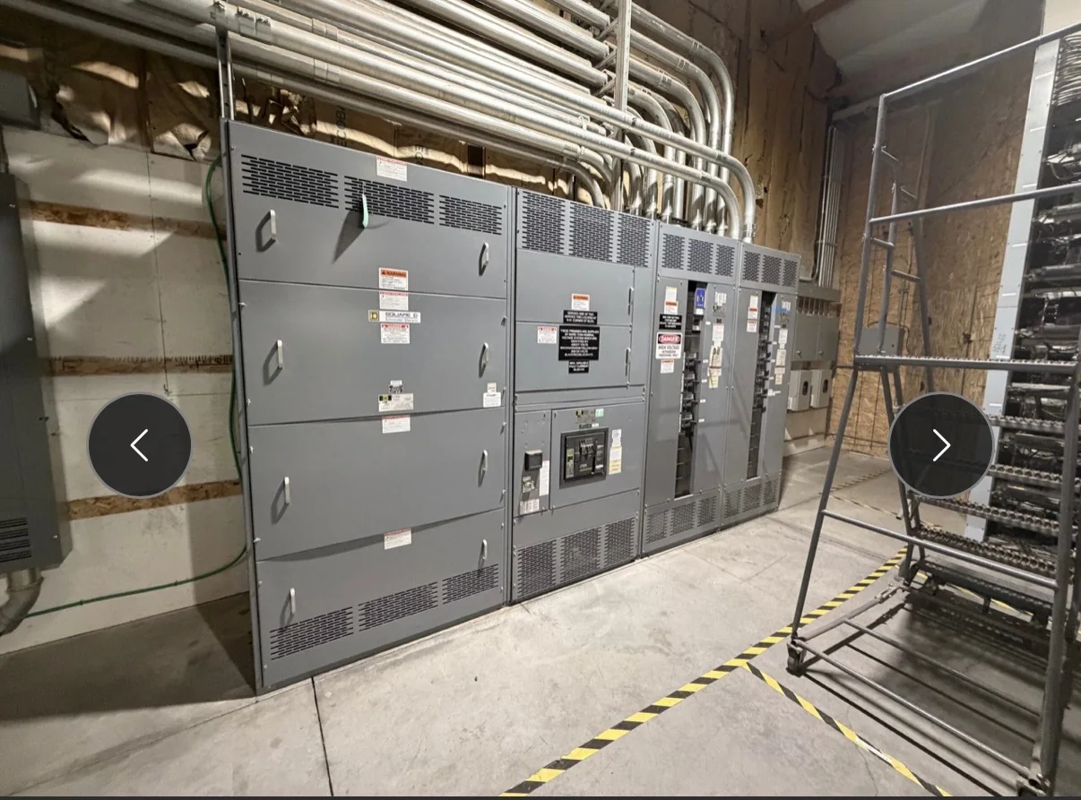
Modernization Starts With the Existing Distribution System
A switchgear modernization project begins by documenting what the existing equipment must do, not by selecting a new lineup from a catalog. Record the system voltage, available fault-current information, bus arrangement, source configuration, protective-device functions, metering needs, and connected loads. Confirm which sections serve critical processes and whether emergency or standby sources are present. These details affect how a replacement assembly is specified and how the changeover can be planned. Existing drawings may be incomplete or may not reflect field changes, so reconcile them with site records and qualified field verification. For a U.S. manufacturer building new equipment to project requirements, a clear basis of design helps resolve questions early, reduces avoidable revisions, and gives procurement and engineering teams a common reference.
Translate Operational Needs Into Procurement Requirements
A request for a replacement switchboard should identify both electrical requirements and operating priorities. Specify the intended service, incoming and outgoing circuit functions, required protective-device features, instrumentation, control interfaces, and any preferred component manufacturers where compatibility matters. Include expected load changes, planned capacity additions, and constraints on equipment footprint or access. Avoid treating an existing nameplate as a complete specification: past modifications, changed loads, or revised utility conditions may alter what the new assembly needs to accommodate. Procurement teams should distinguish mandatory requirements from preferences and ask vendors to identify assumptions, exceptions, and information still needed. This approach makes bids easier to compare and limits late clarification cycles. Final ratings, construction details, standards, and equipment suitability must be established for the specific project.


Plan Replacement Around Shutdown and Continuity Needs
The equipment replacement sequence can be as consequential as the equipment selection. Identify acceptable outage windows, loads that cannot be interrupted, temporary operating arrangements, and the parties responsible for switching, installation, testing, and return to service. A planned outage is not a substitute for qualified electrical work or required de-energization and verification. Where continuity is critical, engineers may evaluate staged replacement, temporary distribution, or other project-specific approaches; each requires careful review of protection, capacity, connections, and site safety. Confirm the scope boundary between the new assembly and existing conductors, controls, grounding, and upstream protection. The manufacturer’s drawings and equipment interface information can support planning, but field conditions and the approved work plan govern execution. Agreeing on responsibilities early helps avoid schedule conflicts during a narrow outage window.
Check the Room, Access Route, and Connection Interfaces
A new lineup must fit the electrical room and the route used to deliver it, not merely the footprint shown on an old drawing. Verify room dimensions, door and corridor clearances, ceiling obstructions, floor conditions, cable entry locations, working space, and the path for moving equipment into position. Confirm whether existing conduits and conductors can reach the proposed termination points and whether control wiring, grounding connections, or bus interfaces need revision. Site measurements should account for construction changes and equipment that may have been added since the original installation. These checks are especially important when replacement must occur in a confined room or operating facility, where access restrictions can affect assembly configuration and installation sequencing. Resolve uncertain interfaces before approving final drawings, since late changes can affect both fabrication and site work.
Review Drawings, Components, and Applicable Standards
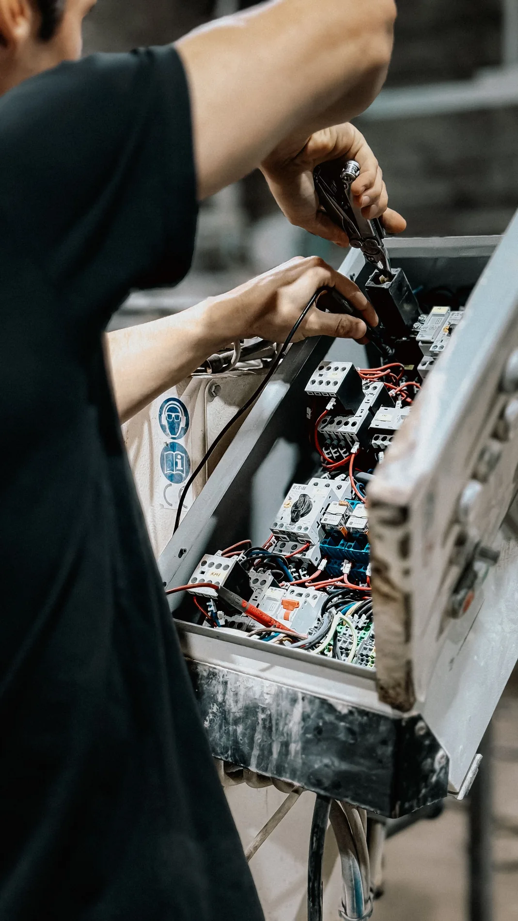
Before releasing a custom build, review the proposed arrangement against the project’s electrical one-line, control requirements, room layout, and interface schedule. Check circuit designations, device functions, cable and bus connections, metering, and any specified communications or auxiliary power. Ask for clarification where existing documentation conflicts or omits a requirement rather than allowing an assumption to become a fabrication detail. UL 891 applies to appropriately evaluated low-voltage switchboard assemblies; it is not a blanket certification for medium- or high-voltage equipment, and a stated offering does not establish that every assembly carries a UL label. The project team should confirm the applicable standards, evaluation expectations, and documentation for the actual equipment. American components may be specified where they suit the design, but component choice and compatibility remain project-specific.
Coordinate Build Timing, Delivery, and Closeout Records
Discuss schedule expectations with the manufacturer when the specification is taking shape, because design approvals, component selections, and unresolved site information can influence the production sequence. Request a schedule basis and identify the dates needed for drawing review, approved submittals, shipment, receiving, and the planned outage; do not treat an estimated delivery window as a guarantee. Nationwide shipping can support projects in different regions, but the receiving plan still needs a confirmed delivery point, access restrictions, unloading arrangements, and coordination with the installation contractor. At closeout, organize approved drawings, equipment identification, component information, and applicable test or evaluation records supplied for the project. Complete records help facility staff maintain the new distribution equipment and understand its boundaries. Verify the required documents and their delivery timing in the purchase scope.