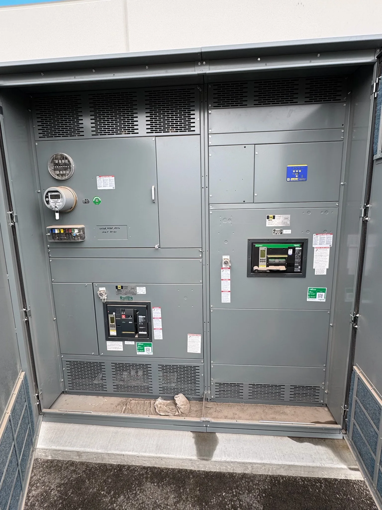
Define What the Replacement Must Accomplish
A switchgear replacement in Pearland starts with the operating problem, not a presumed one-for-one equipment swap. Document what is driving the project: obsolete components, unavailable support, condition concerns, a capacity change, or a planned facility upgrade. Then establish which loads must remain available, what outage windows are realistic, and whether the work covers the complete lineup or selected sections. These distinctions affect equipment arrangement, connection points, protection coordination, and the construction sequence. Gather existing drawings, nameplate photographs, maintenance records, and available fault or coordination studies before requesting a proposal. If records conflict with field conditions, flag that early rather than treating old drawings as verified. A clear scope helps the manufacturer identify missing inputs and helps the facility team compare proposals on equivalent technical and operational assumptions.
Build the Specification Around Verified Site Data
Electrical details determine whether replacement equipment will fit and operate within the existing distribution system. Confirm system voltage, phase, frequency, available fault current, bus arrangement, grounding method, incoming and outgoing conductor details, protective-device requirements, and the intended service configuration. Record enclosure dimensions, access clearances, cable entry direction, and the location of adjacent equipment. For a retrofit, document the existing manufacturer and model where identifiable, but do not assume that a new assembly can reuse old sections, bus, or connections without engineering review. Provide the latest one-line diagram and identify known changes since it was prepared. Missing or uncertain information should be listed as an open item for engineering, not silently converted into a design assumption. Final ratings, compatibility, and applicable standards depend on project-specific evaluation.


Plan Protection and Controls for the Actual Loads
A replacement can have the correct physical footprint and still create problems if protection and control requirements are overlooked. Identify the loads served, motor starting or other unusual operating characteristics, upstream protective devices, and any coordination or arc-flash study requirements available to the project team. Specify metering, alarms, interlocks, communications, and control power only where the operating plan requires them; interfaces can differ substantially between facilities. If a new device or trip unit changes protection functions, have qualified engineering personnel assess its effect on the system rather than treating it as a component substitution. Include desired control diagrams, communications protocols, and points that must report to building or process systems. These details help define a usable submittal and reduce late changes, while final settings and field acceptance remain subject to project review and authorized commissioning.
Set a Schedule That Accounts for More Than Fabrication
Discuss timing with the manufacturer using the actual scope, approval path, and required delivery date—not a general expectation for short lead times. Custom configurations, component selection, engineering questions, drawing review, and customer revisions can affect the schedule. Identify who will approve submittals, how quickly decisions can be made, and whether the facility requires witness points or specific documentation before release. Separately map the outage request, demolition, installation, inspection, testing, and return-to-service activities with the project’s electrical contractor and facility operations team. A shipment date is not the same as a completed replacement, particularly where production, tenant, or life-safety loads constrain access. Request current availability and a project-specific schedule in writing, and keep unresolved design inputs visible so planning does not depend on an unconfirmed assumption.
Check Pearland Site Access and Delivery Conditions
Delivery planning for a Pearland facility should reflect the actual receiving point, not just the city name on the destination. Confirm truck access, gate procedures, delivery hours, unloading responsibility, staging space, and the route from receiving to the electrical room. Large assemblies may require a review of door openings, corridors, turns, floor capacity, and handling equipment before the shipping configuration is finalized. In the Houston area, heat, humidity, and heavy rain can complicate exposed staging and outdoor handling, so establish who will protect equipment and how long it may remain outside. Coordinate those details with the facility and carrier, including any restrictions on advance delivery. Nationwide shipping is available as an offering, but freight arrangements, packaging, delivery timing, and site readiness must be confirmed for each project.
Review Submittals, Scope, and Acceptance Responsibilities
Before authorizing production, compare the proposal and submittal package against the approved project requirements. Check lineup dimensions, ratings, device functions, connection provisions, enclosure details, accessories, and the drawing revision being priced. Confirm what is included or excluded for freight, unloading, installation, existing-equipment removal, field connections, testing, and startup; these responsibilities are often divided among the manufacturer, contractor, and owner. A U.S. manufacturer can discuss American component options and custom builds, while actual component selection and availability remain project-specific. UL 891 applies to appropriately evaluated low-voltage switchboard assemblies; it is not a blanket certification for medium- or high-voltage equipment, and any required evaluation or label must be confirmed for the specified assembly. Close open questions before release, then coordinate de-energized work, inspection, testing, and turnover records with qualified project personnel.