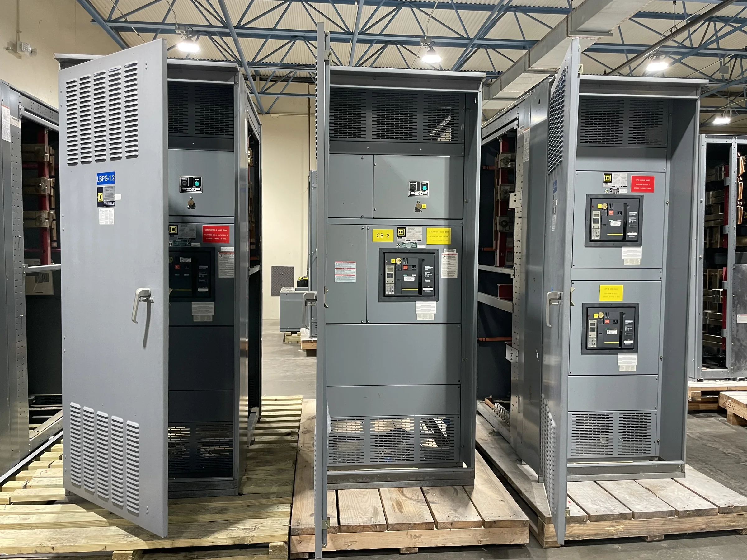
Define What the Replacement Must Accomplish
A switchgear replacement begins with the electrical function the new equipment must perform, not just the nameplate on the existing lineup. Document the system voltage, frequency, available fault current, continuous load, number of sources, grounding arrangement, and intended future loads. Identify whether the equipment is a low-voltage switchboard, switchgear lineup, or medium-voltage assembly; these terms describe different equipment and should not be treated as interchangeable. The distinction affects construction, protective-device coordination, clearances, and applicable evaluation requirements. Gather one-line diagrams, equipment schedules, and existing trip or relay settings where available, then flag gaps for engineering review. Accurate starting information helps the manufacturer develop a project-specific configuration and reduces the risk of quoting equipment that fits the description but not the electrical duty.
Verify System Compatibility and Protection
Replacement equipment must coordinate with the system around it, including upstream protection, downstream feeders, transformers, generators, and any utility requirements. Provide available fault-current data and identify the protective devices expected to remain in service; interrupting ratings, bus bracing, and coordination cannot be selected reliably from a general equipment label alone. If the project changes loads or sources, request review of the one-line diagram and protection study assumptions rather than carrying forward old settings by default. For low-voltage switchboard assemblies, UL 891 may be relevant when the assembly is appropriately evaluated for that standard; it does not establish blanket coverage for medium- or high-voltage gear. Ask the supplier to identify the proposed equipment’s applicable standards and evaluation basis, and have the responsible engineer confirm suitability for the installation.


Resolve Footprint, Access, and Interface Details
A lineup that meets electrical requirements can still create costly field work if its dimensions or connection points do not match the site. Send equipment-room plans, elevation drawings, door and aisle clearances, conduit entry locations, cable bend-space constraints, and the existing lineup’s connection details. Confirm whether the installation must preserve wall access, overhead lifting space, or a defined route from the receiving area to the room. Note bus transitions, cable terminations, neutral and ground connections, and control wiring interfaces that may need adaptation. Existing drawings can be incomplete or outdated, so clearly distinguish measured conditions from assumptions and arrange a site survey when the project requires one. Reviewing these details before release helps identify layout conflicts early, when changes are less disruptive than field modifications.
Plan the Outage and Installation Sequence
The replacement schedule depends on engineering approvals, submittal review, fabrication, shipping, site readiness, and the planned outage—not a single quoted production interval. Share the required in-service date and the consequences of missing it, but ask the supplier to confirm current project-specific timing before making commitments to operations. Identify shutdown windows, temporary-power needs, switching responsibilities, demolition limits, and whether the old and new equipment can be staged separately. Work on electrical equipment must be planned and performed under appropriate safety procedures, including de-energization and verification before work begins; do not build an installation plan around energized replacement work. A detailed sequence lets procurement, engineering, the electrical contractor, and facility staff surface dependencies early, coordinate approvals, and reduce the chance that equipment arrives before the room, outage, or crew is ready.
Coordinate Shipping and Receiving Constraints
Nationwide shipping can support projects across different regions, but delivery planning still needs to reflect the actual site and equipment configuration. Provide the delivery address, receiving hours, dock or unloading limitations, access restrictions, and any requirements for advance notice, appointment scheduling, or special handling. Confirm shipment dimensions and weights against the route into the building, not merely the truck access point; a doorway, elevator, corridor turn, or floor loading limit may control how sections can be received and moved. Establish who inspects the shipment, documents visible damage, and secures equipment after arrival. If multiple sections or accessories are involved, align the packing and delivery sequence with the installation plan. These checks help avoid storage problems, handling delays, and damage before the assembly reaches its prepared location.
Review Submittals, Scope, and Quote Assumptions
Before approving a purchase, compare the proposal and submittal package with the project documents line by line. Check the stated voltage, bus arrangement, device functions, metering, control requirements, enclosure details, entry provisions, and interfaces against the design, while marking every exception for resolution. Clarify what is included, such as drawings, review cycles, accessories, and shipping, and identify items assigned to the engineer, contractor, or owner. Ask how revisions after approval may affect price or schedule, and confirm which site conditions remain unverified. A U.S. manufacturer can discuss custom builds and American components, but exact component selections, standards, availability, and configuration must be confirmed for the project. Clear written assumptions help procurement compare bids accurately and give engineering and installation teams a reliable basis for coordination.