Define the Retrofit Scope Before Selecting Equipment
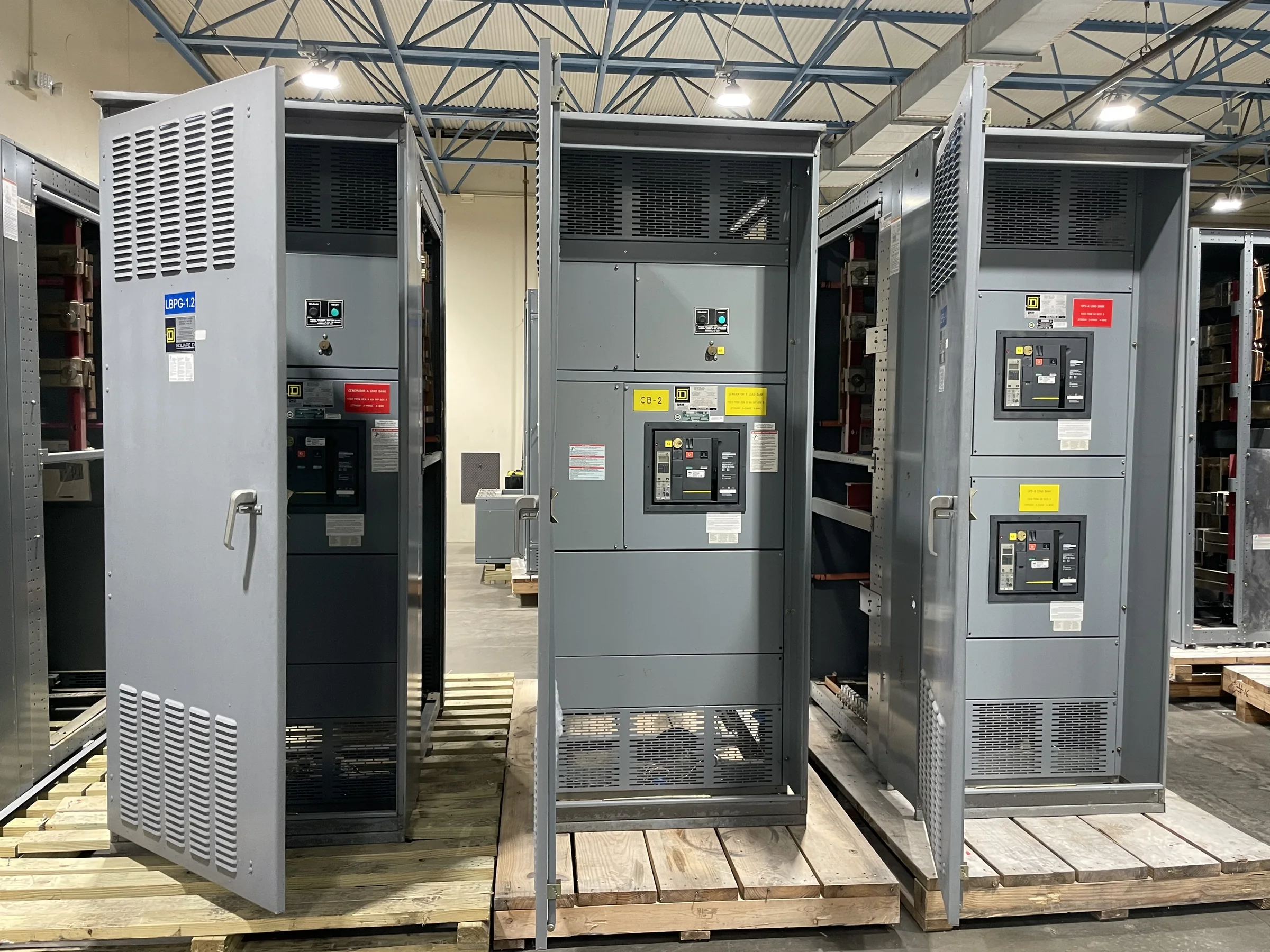
A switchgear retrofit can mean replacing a complete assembly, integrating new equipment with retained sections, or coordinating replacement distribution equipment with a broader facility upgrade. Establish the scope before requesting pricing: identify the affected lineup, connected loads, normal and alternate sources, and any equipment that must remain in service during the project. This distinction matters because an assembly designed for a clean replacement may not fit a phased installation or a constrained outage. Gather existing one-line diagrams, equipment schedules, nameplate photographs, and available drawings, then flag discrepancies for engineering review. A U.S. manufacturer can use that information to discuss a new build suited to the project, while final configuration, compatibility, and applicable evaluation remain subject to detailed review.
Verify Electrical Ratings and System Conditions
Replacement gear must be evaluated against the actual electrical system, not selected by enclosure dimensions alone. Confirm system voltage, phase, frequency, continuous load, available fault current, grounding arrangement, and source configuration using current project records and qualified engineering analysis. Where existing protection or upstream equipment is changing, review coordination and interrupting requirements together; a mismatch can compromise protection or prevent the proposed assembly from serving its intended role. Document environmental conditions such as indoor or outdoor exposure, ambient temperature, contamination, and ventilation constraints, since these can affect construction and installation decisions. Treat ratings, standards, and compatibility as project-specific items for written confirmation. For low-voltage switchboard assemblies, UL 891 may be relevant when the assembly is appropriately evaluated; it does not apply as a blanket claim to all switchgear.


Resolve Interfaces, Controls, and Retained Equipment
The most difficult retrofit interface may be a cable entry, bus connection, control circuit, or protective-device scheme rather than the main enclosure. Record cable sizes and entry directions, conduit locations, bus arrangements where documented, control voltages, metering needs, and interfaces to generators, transformers, or building controls. If any existing components are to remain, identify their manufacturer, type, condition, and documented ratings; do not assume that physical fit establishes electrical or mechanical compatibility. This information helps the manufacturer and project engineer identify questions before drawings are finalized, reducing avoidable redesign and field changes. Mark unknowns explicitly instead of treating older records as verified. Final interface details should be checked against approved drawings and applicable engineering requirements before equipment is released for manufacture.
Plan Outages, Installation, and Site Access
A sound equipment proposal must account for how the old lineup will be removed and the new assembly moved into position. Measure access doors, corridors, turns, floor openings, overhead obstructions, and the available staging area, then confirm shipping-piece dimensions and weights during design coordination. Existing foundations, anchorage, cable routing, and working clearances also require review; a lineup that fits the electrical room may still be impossible to install through the building route. Coordinate outage duration, temporary power needs, contractor responsibilities, and required shutdown approvals with facility operations. All work on electrical equipment must be performed under an approved safety program, with equipment de-energized and verified before work begins. The project schedule should reflect site readiness and outage approvals, not just factory build timing.
Prepare a Complete RFQ and Review Submittals
A useful request for quotation gives the manufacturer enough information to identify scope, engineering questions, and delivery requirements without implying unverified conditions. Include the one-line diagram, equipment schedule, available fault-current information, operating sequence, site conditions, preferred replacement boundaries, and requested documentation. State whether the project includes installation, demolition, startup, or field services rather than assuming these are included in an equipment quotation. During submittal review, compare the proposed ratings, dimensions, cable and bus interfaces, protective-device details, control functions, and exceptions against the project documents. Resolve deviations in writing before approval for manufacture. Request drawings and a documented list of required customer decisions so that engineering review, purchasing approval, and construction planning can proceed from the same confirmed equipment basis.
Coordinate Build Timing, Delivery, and Receiving
Discuss timing early, but base the schedule on the approved scope, engineering decisions, component availability, and the project’s required review cycle; no generic lead-time estimate guarantees delivery for a specific build. Identify decision dates for drawings, outstanding technical questions, and any owner-furnished information that could affect release. A U.S. manufacturer offering custom builds, American components, short lead times, and nationwide shipping can discuss options against those project details, with availability and schedule confirmed for the order. Before shipment, establish the delivery address, receiving hours, unloading equipment, carrier access, storage conditions, and who will inspect and document the shipment. Protect equipment from moisture, dust, impact, and unsuitable storage conditions as directed by the manufacturer. Aligning delivery with site readiness avoids premature receipt, added handling, and installation delays.