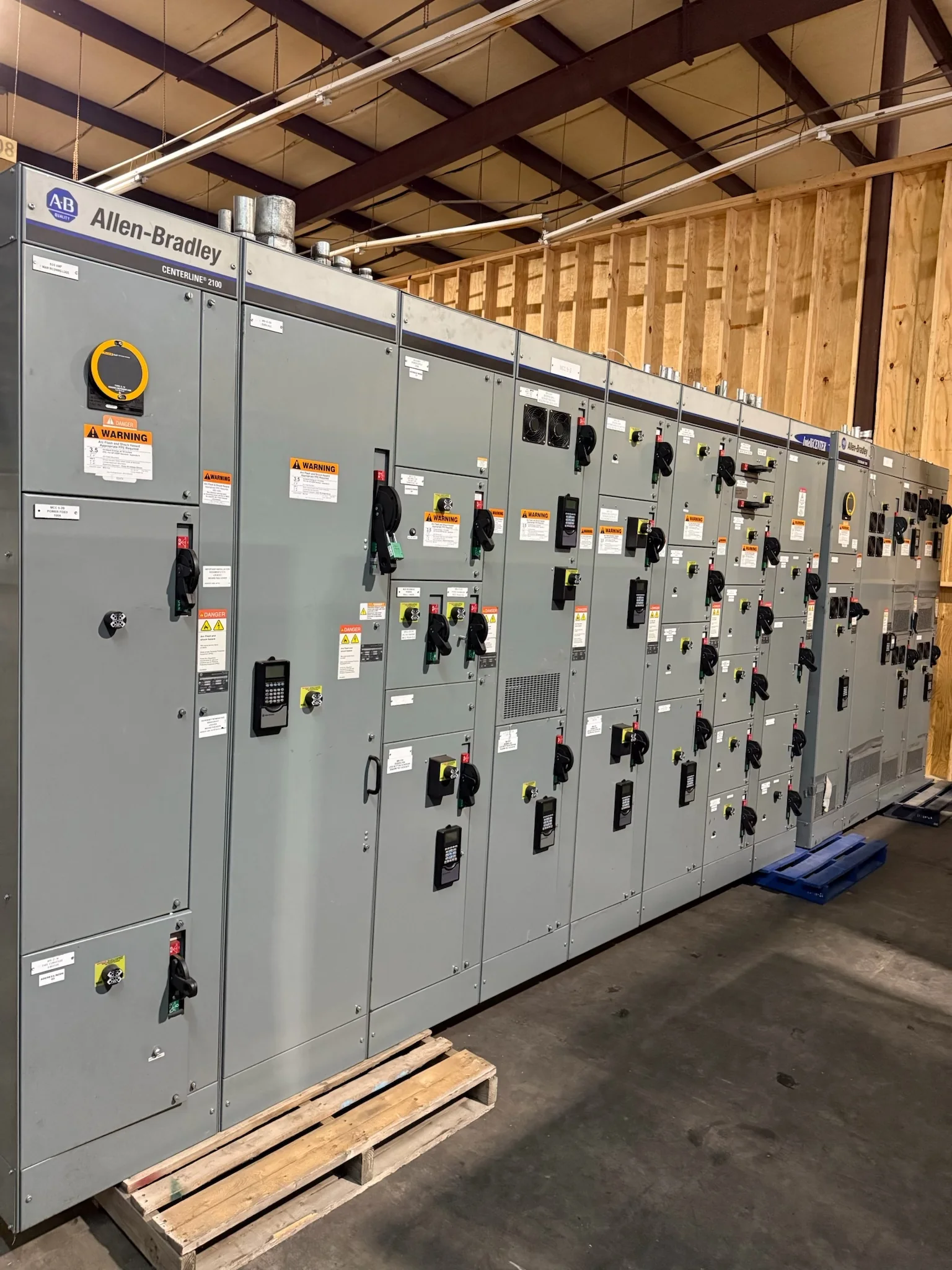
What a Service Entrance Switchboard Does
A service entrance switchboard is the equipment at the point where utility-supplied power enters a facility’s electrical distribution system. It provides a defined location for the service disconnecting means and, depending on the design, service overcurrent protection, metering provisions, and distribution to downstream equipment. Its role is not interchangeable with every panelboard or distribution switchboard: equipment used on the service side of the installation must be suitable for that position and coordinated with utility requirements and applicable electrical codes. That distinction matters during replacement work, because a downstream board may not have the construction or functions required at the service entrance. Confirming the intended service point, system voltage, phase, and distribution arrangement early helps the project team identify the right equipment category before requesting a quote.
How Service-Rated Design Affects Equipment Selection
Selection begins with the electrical system and the way the utility and facility divide responsibility. Engineers and procurement teams should document nominal voltage, phase, frequency, available fault current where established, service conductor arrangement, grounding method, and the required disconnecting and overcurrent functions. The utility may specify metering location, compartment access, or other service conditions; those requirements should be checked before the switchboard layout is finalized. A mismatch can affect both approval and field installation, even when the equipment appears to fit the one-line diagram. Interrupting ratings, bus ratings, device types, and the form of service equipment are project-specific choices, not assumptions to carry over from an older unit. Provide the current one-line diagram and utility criteria with the inquiry so the manufacturer can review the intended application.


Documents That Help Define the Build
A useful equipment package translates design intent into information the manufacturer can evaluate. Include the latest one-line diagram, equipment schedule, specifications, site voltage and grounding details, utility service requirements, and any stated short-circuit or coordination criteria. Show the incoming and outgoing cable or bus connections, preferred entry locations, available working and equipment space, and interfaces with transformers, generators, or other distribution gear. If replacing existing equipment, provide nameplate data, clear photographs, measured dimensions, and the condition and location of the existing conductors; visual similarity alone does not establish compatibility. Identify required metering, control wiring, accessories, and submittal expectations. Complete documents reduce avoidable clarification cycles and expose conflicts—such as a specified cable entry that meets a wall or conduit bank—before fabrication details are approved.
Site Conditions and Installation Constraints
The switchboard must work in the room and on the route used to get it there, not just on the drawing. Verify the equipment footprint, door swing, working clearances, ceiling height, floor or housekeeping-pad conditions, and access for anchoring and conductor termination. Check corridors, door openings, turns, elevators, loading areas, and the final move into the electrical room; shipping sections that cannot pass the route can disrupt an installation despite correct electrical design. Environmental exposure also matters: indoor or outdoor placement, moisture, dust, corrosive agents, temperature, and ventilation can affect enclosure and equipment selection. Existing facilities may impose shutdown windows and restrictions on staging or rigging. Share site dimensions and delivery constraints during quoting, then have qualified project personnel confirm final placement, installation, and code requirements.
Lead Time, Review, and Delivery Coordination
Project timing depends on the approved scope, design completeness, selected components, review cycles, and current manufacturing and transportation conditions. A U.S. manufacturer offering custom builds and short lead times can discuss a schedule, but no delivery period should be treated as guaranteed until the specific configuration and order requirements are reviewed. Clarify when submittals are needed, who approves them, whether utility review is required, and what decisions remain open. Late changes to devices, cable entry, enclosure details, or metering provisions may affect both design and schedule. Coordinate the requested ship date with site readiness, receiving hours, unloading equipment, storage conditions, and the planned outage or installation sequence. Nationwide shipping does not remove the need to confirm delivery access, packaging expectations, and responsibility for receiving and moving the equipment.
Replacement, Retrofit, and Standards Review
Replacing a service entrance switchboard is an opportunity to verify the complete installation rather than reproduce an old nameplate. Compare the existing service arrangement with current utility requirements, system conditions, available fault current, downstream protection, conductor routing, and the space available for new equipment. A replacement may require changes to feeders, terminations, metering, grounding, or the outage plan; compatibility must be established by the responsible engineering and installation teams. Specify the applicable standards and evaluation expectations for the actual equipment. UL 891 applies to appropriately evaluated low-voltage switchboard assemblies; it is not a blanket certification for medium- or high-voltage gear, and a standard reference alone does not establish that a particular assembly carries a UL label. Request project-specific submittals and confirm ratings, approvals, and availability before release.