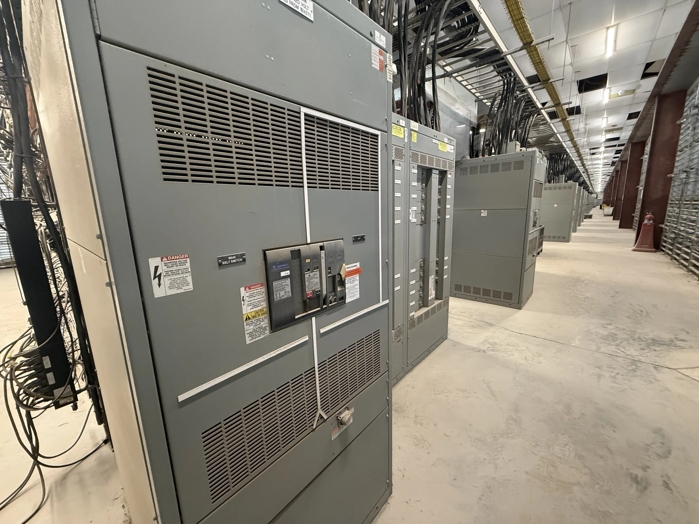
What an Automatic Transfer Switch Does
An automatic transfer switch (ATS) monitors the normal power source and, when its voltage or frequency falls outside configured limits, transfers designated loads to an alternate source, commonly an emergency generator. When normal power returns and remains acceptable for the programmed interval, the control system can transfer the load back. The switch changes the electrical connection; it does not create backup power, start every type of generator, or guarantee uninterrupted service. Transfer can involve a brief interruption, and the outcome depends on the source, equipment, controls, and load. For procurement, define which circuits must remain supplied and what interruption they can tolerate. That distinction helps determine whether an ATS is appropriate or whether the project calls for a different power-continuity strategy.
Choose the Transfer Arrangement Around the Loads
A project may use open-transition transfer, in which the load disconnects from one source before connecting to the other, or another arrangement suited to its operating requirements. The choice affects the interruption, source coordination, and equipment complexity. Loads that can ride through a short break may be served differently from processes sensitive to even a momentary loss; do not assume that an ATS provides seamless power. Engineers should identify critical, life-safety, legally required, and optional loads as applicable to the facility and governing requirements, then determine how they are grouped and sequenced. Motor loads, electronic controls, and transformer inrush can influence transfer behavior and source sizing. Document the intended sequence and load priorities early so the equipment configuration reflects actual operation rather than a broad label such as “emergency power.”


Confirm Electrical Ratings and System Compatibility
An ATS must be suitable for the system it serves, not selected by amperage alone. Confirm system voltage, phase, frequency, available fault current, conductor arrangement, grounding method, and the characteristics of both normal and alternate sources. The engineer should also verify the transfer equipment’s required ratings and protective-device coordination against the project’s fault study and applicable codes. Neutral switching, service equipment use, bypass-isolation needs, and the location of overcurrent protection can affect the assembly and its installation. These details are project-specific; a product description cannot establish compatibility or code compliance on its own. Provide one-line diagrams and source information when requesting a quotation, and have the responsible electrical professional resolve discrepancies before release. A mismatch can affect safety, operation, approvals, and replacement fit.
Coordinate Controls, Generator Signals, and Testing
Reliable operation depends on the relationship between the ATS controls and the alternate source. Establish how the switch will signal a generator to start, how source-available conditions are determined, and what delays or return-to-normal sequence the application requires. Generator controls, remote annunciation, building automation, and fire or life-safety interfaces may need defined contacts or communications; confirm interface requirements rather than assuming they are included. Specify any load-shed or staged-load sequence where generator capacity is limited. During design review, document the intended sequence of operation and identify who supplies, wires, programs, and verifies each interface. Commissioning should test the approved sequence under controlled conditions, with qualified personnel and required precautions. Clear responsibility boundaries reduce late field changes and help ensure the installed system behaves as operators expect.
Plan the Enclosure, Access, and Installation Conditions
The physical installation can rule out an otherwise suitable ATS. Compare the proposed assembly dimensions, working clearances, cable-entry direction, bend space, conduit routes, ventilation, and service access with the actual electrical room or outdoor location. Existing gear may constrain door swing, lifting access, wall space, or the path from the receiving area to the final pad. Environmental exposure, ambient conditions, seismic or other site requirements, and enclosure selection should be reviewed for the specific location and applicable design criteria. For replacement work, record the existing equipment identification, connections, available space, and any shutdown constraints; do not assume a new assembly is a direct physical or electrical fit. Early field verification gives the manufacturer and project team a chance to resolve constructability questions before drawings are approved.
Prepare a Quote Package and Coordinate Delivery
A useful RFQ package gives the manufacturer enough information to price the intended equipment without treating unresolved details as settled. Include the one-line diagram, load and source data, transfer sequence, required ratings, enclosure and access conditions, control interfaces, applicable project standards, and requested submittal documents. State whether the work is new construction or replacement and identify review milestones, site receiving limits, unloading arrangements, and the required delivery destination. A U.S. manufacturer can discuss custom builds, American components, nationwide shipping, and timing against the project requirements, but exact configuration, availability, and delivery dates require confirmation. If a low-voltage switchboard assembly is involved, specify any applicable UL 891 evaluation requirements; that standard is not a blanket certification for every ATS or for medium- and high-voltage equipment. Resolve scope and documentation before release.